I have started assembling a PSU out of some scrap.
My unloaded power transformer delivers approx. 390-0-390 volts AC at the secondary.
After diode rectification, I obtain around 358 Vdc (again, unloaded).
However, if I connect a power supply filtering/smoothing circuit (50uF/2.2K/50uF) to the output, the voltage at C1 and/or C2 jumps to over 500 Vdc - again, this is without any additional circuitry to load down the transformer.
Is this normal? Would B+ return to safer levels under load? Can I damage my input capacitor (rated for a mere 500V) by running the PSU unloaded?
I would like to build another RH84, wonder how I'd go about settling on or around 300 Vdc under load with this particular transformer?
Why does the voltage increase after C1, C2?
Thanks,
What are you using to measure? It sounds like you're not taking into account the waveforms and their peak/average/RMS values.
I'd have to draw it & scan. But it's textbook stuff really. Full wave rectification via a pair of UF4007 diodes > pi-shaped filter section comprising 50uF shunt capacitor/2K2 series resistor/50uF shunt capacitor. That's it. I haven't hooked it up to any load or "circuit" as such, which may be the problem.
Hi!
500V sounds about right if unloaded. Unloaded the DC output rises to 1.4 times the AC secondary voltage. Make sure your PSU has some bleeder resistors installed which drain the caps when the PSU is turned off. Otherwise the caps stay charged and you could get a zap when working on it.
Best regards
Thomas
After you rectify it you will get approxomately 390v X .9= 351V.
When you add the filter caps you will get 390 X 1.142 = 551Vdc.
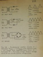
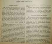
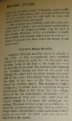
Here is an excerpt taken from page 111 of the ARRL 1978 handbook.
Enjoy !!
jer 🙂
When you add the filter caps you will get 390 X 1.142 = 551Vdc.
Here is an excerpt taken from page 111 of the ARRL 1978 handbook.
Enjoy !!
jer 🙂
Attachments
Sounds right to me , i would use a pair of capacitors in series (remember to double the uF) with bleed resistors across each one terminals , using 2 caps rated 100uF-400V in series you get a cap capable of 50uF at 800V (in teory) , 600V for safety ...
The average DC of a rectified but not smoothed sine wave is about 90% of the original AC RMS voltage. 90% of 390V is 351V. You measured 358V. It all looks OK to me.
use higher voltage caps....... the voltages are correct...
as to how much the voltage will drop when the system is loaded will depend on the transformer your are using - ie the internal resistance of the transformer and how much current it is designed to provide and how much current is being drawn...without these parameters/details, impossible to tell how much the expected drop will be
as to how much the voltage will drop when the system is loaded will depend on the transformer your are using - ie the internal resistance of the transformer and how much current it is designed to provide and how much current is being drawn...without these parameters/details, impossible to tell how much the expected drop will be
You might want to consider using what's called a choke-input filter, which will give a lower loaded voltage with some other advantages. Unloaded voltage (including start-up!) will still be the same very high voltage, so you'll still need to allow for that when choosing caps.
All good fortune,
Chris
All good fortune,
Chris
- Status
- Not open for further replies.
- Home
- Amplifiers
- Power Supplies
- Measuring volts on an unloaded PSU secondary