I'm trying to help a friend of mine to measure and optimize his own 2 way bookshelf speaker xover. He has an Omnimic system, the mike is calibrated with the right Dayton data file. Obviously he doesn't have an anechoic room.
The first attempt was not encouraging. The results were all over, with lots of dips and peaks, well beyond of what we were expecting. There were probably some room reflections, but overall the results seem to be pretty useless for fine tuning the xover.
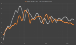
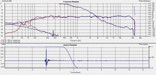
We then decided to measure some well regarded speakers, namely a B&W 802 Matrix Series 80 and a monster 150 lb. Infinity Kappa 100 tower. These are far field measurements, in a more sizeable room (25 x 20 x 10 ft.), with exactly same Omnimic settings for both.
Forget about my friends bookshelves for a moment, since the results (attached) with the B&W and Infinity left us completely confused. What do I see in these results? As expected, the Infinity has likely a better bass and HF responses (no wonder, since it is bass reflex with 2 12" woofers specified down to 30Hz, it is also a 5 way speaker and has at the top an Emit B ribbon tweeter). The B&W is a closed box, so the LF (also 2 12" woofers) rolls sooner.
However, other than that, the same wild response ripple (room reflections?)that don't help understanding the speaker properties in the most audible range of the audio spectra. Besides, where is the huge delta in the efficiency? The Infinity is spec'd at 89dB while the B&W 802 Matrix Series 80 are much less efficient, at 85dB.
Needless to say, at this point my friend is pretty disappointed after investing a sizeable amount of cash in the Dayton measurement tools (and I take part of the heat, since I recommended them as a low cost solution).
So the question is, how do you measure finished speakers with a standard tool like Omnimic, and no anechoic room, to get results useful for xover optimisation?
P.S. Y axis is in dB, but not calibrated for SPL. The phase ripple is not even worth posting, it's jumping all over. I'll post the impulse responses later.
The first attempt was not encouraging. The results were all over, with lots of dips and peaks, well beyond of what we were expecting. There were probably some room reflections, but overall the results seem to be pretty useless for fine tuning the xover.
We then decided to measure some well regarded speakers, namely a B&W 802 Matrix Series 80 and a monster 150 lb. Infinity Kappa 100 tower. These are far field measurements, in a more sizeable room (25 x 20 x 10 ft.), with exactly same Omnimic settings for both.
Forget about my friends bookshelves for a moment, since the results (attached) with the B&W and Infinity left us completely confused. What do I see in these results? As expected, the Infinity has likely a better bass and HF responses (no wonder, since it is bass reflex with 2 12" woofers specified down to 30Hz, it is also a 5 way speaker and has at the top an Emit B ribbon tweeter). The B&W is a closed box, so the LF (also 2 12" woofers) rolls sooner.
However, other than that, the same wild response ripple (room reflections?)that don't help understanding the speaker properties in the most audible range of the audio spectra. Besides, where is the huge delta in the efficiency? The Infinity is spec'd at 89dB while the B&W 802 Matrix Series 80 are much less efficient, at 85dB.
Needless to say, at this point my friend is pretty disappointed after investing a sizeable amount of cash in the Dayton measurement tools (and I take part of the heat, since I recommended them as a low cost solution).
So the question is, how do you measure finished speakers with a standard tool like Omnimic, and no anechoic room, to get results useful for xover optimisation?
P.S. Y axis is in dB, but not calibrated for SPL. The phase ripple is not even worth posting, it's jumping all over. I'll post the impulse responses later.
Attachments
Last edited:
With the Omnimic (I have one also), window your measurement by clicking on the impulse response plot at the bottom. Click at about the 3 or 4 millisec time and place your mic about 1/2 meter from and on the tweeter axis. When you click on the line you should see the line be red from 0 up to the point where you clicked and black beyond that.
Windowing will take out those pesky response ripples. If you still get some, slowly move the mic closer to the speaker with subsequent further measurements to see if they diminish. If they don't, then there's something wrong with the speaker like serious internal reflections or cabinet resonances, etc....
Also, the speaker should be well off the floor and pointed away from any nearby walls, ceiling or other obstructions. If you can't do this, then you'll need to move the speaker to a place where these reflective surfaces are gone.
Last edited:
Thank you guys, that helped a lot. Still lots to learn about, I knew it's much harder than designing and building audio amplifiers.
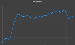
The far field measurement of the Infinity Kappa 100 monster now makes more sense.
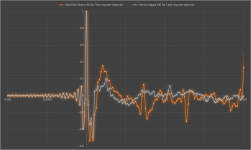
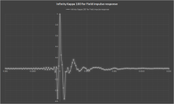
The impulse response is on the ribbon tweeter axis, 2mS window. Is this typical for a ribbon tweeter?
Interesting stuff, wish I had more time and the means to get into...
The far field measurement of the Infinity Kappa 100 monster now makes more sense.
The impulse response is on the ribbon tweeter axis, 2mS window. Is this typical for a ribbon tweeter?
Interesting stuff, wish I had more time and the means to get into...
Attachments
Last edited:
If you're measuring out to 2ms before truncating, the stuff below 500Hz will be meaningless. But you may want to be looking above 1kHz as well- your charts cut off there.
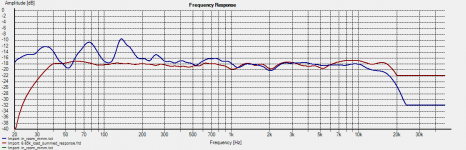
This is a windowed measurement of my prototype speakers using OmniMic to illustrate what a properly windowed measurement looks like. The stuff below 200Hz shouldbe ignored- that's where you take a near-field measurement, then merge it.
This is a windowed measurement of my prototype speakers using OmniMic to illustrate what a properly windowed measurement looks like. The stuff below 200Hz shouldbe ignored- that's where you take a near-field measurement, then merge it.
Attachments

But you may want to be looking above 1kHz as well- your charts cut off there.
I thought it's up to 20k?
Windowing for the merge was 10mS (so down to 100Hz), I corrected, the impulse response is on the ribbon tweeter axis only.
I thought it's up to 20k?
Windowing for the merge was 10mS (so down to 100Hz), I corrected, the impulse response is on the ribbon tweeter axis only.
I would suggest that 4ms is probably the best you could hope for in any normal room (and even that is probably pushing it). I can't even get >4ms measuring outside (though I only have a small back yard). 🙂
Attached is a measurement done outside at 1.3M showing the same measurement as gated, and with 1/8th octave smoothing.
2nd image is the same speaker measured in room at the listening position (with no attempts made to optimise measuring setup. ie was not trying to get quasi anechoic response). again showing gating and 1/8th octave smoothing.
With careful speaker and mic placement, moving furniture around and generally experimenting until you find what works best, you can get pretty good measurements in room, but I would say not far field (in the normal sense of the word). 1M mic distance is the most I would ever try to use in room, and in fact the final measurements (taken outside) I settled on when getting measurements for a crossover at around 300Hz were done at about 0.7M and spliced with nearfield as per the links that jreave has provided.
Tony.
Attachments

Last edited:
Quick questions before sleep: if the speaker has two woofers in parallel, how do you measure or calculate the combined near field response for the blending process?
Hey, thanks a lot for these links - and to Jeff and Charlie too if you're out there.
-- Jim
Yes, try to run the measurement during a quiet period.How do you deal with wind noise outside though? Do you just time it not to be during a breeze?
Generally outside measurements are limited to frequency response only since the background noise floor is likely to be poor even during a 'quiet' period. If you measure loud enough, the background noise should be a good 30dB or so quieter and really ceases to be an issue anymore. 65dB+95dB = 95.27dB
Interesting article from Bagby, but it's a lot of work I'm not sure I fully understand the benefits of yet for crossover design. I'd rather have imprecise far-field that incorporates the baffle and room effects than attempt to measure perfectly quasi-anechoically and create an ultimately sterile or mismatched speaker.
Again, I need to do more reading. Maybe if my current speakers had failed I would have a different perspective, but they didn't. They sound flipping amazing. 😀
I just got D'Appolito's book, maybe he'll help rain down knowledge and have it stick where others have failed to in this area.
Best,
Erik
Last edited:
How do you deal with wind noise outside though? Do you just time it not to be during a breeze?
Pretty much yes! wait for a nice still sunny day. Not too hard where I am, but yes I can see that might be a challenge in some parts of the world!
Once you have that you still potentially have to deal with airplanes, cars, trucks etc, but a bit of patience usually helps.
Tony.
Quick questions before sleep: if the speaker has two woofers in parallel, how do you measure or calculate the combined near field response for the blending process?
It will only be an issue if they do not add the same (which is unlikely) If you want to be 100% certain, measure each individually and sum the result, as the near field needs to be adjusted in level to match the far field anyway, if both woofers contribute the same you could just measure one and adjust level accordingly to splice in with the second.
Tony.
Interesting article from Bagby, but it's a lot of work I'm not sure I fully understand the benefits of yet for crossover design. I'd rather have imprecise far-field that incorporates the baffle and room effects than attempt to measure perfectly quasi-anechoically and create an ultimately sterile or mismatched speaker.
Phase data is the main reason... with the typical curve you get from doing in room measurements if you are trying to do a crossover around 300Hz or lower you are going to struggle getting good phase matching with real measurements.
I tried using in room MMM measurements for doing my crossover design between my MTM's and 10" woofers, but it was not a success. Using the methods linked was much better. even with a CTC distance between the woofer and the tweeter of nearly 0.8M and a crossover frequency around 270Hz I am getting very good integration. MUCH better than I thought would have been possible with such a sub optimal setup. It was just supposed to be a stopgap till I can redo the cabinets for the 10" drivers, but I was pleasantly surprised. Without going to this trouble, I do not believe it would have been a success.
I still have some issues in room. Big (+-5db 1/6th octave smoothed) peaks and dips below 200Hz. That is something I'm not sure would be better addressed in the crossover or through EQ (or ideally through room treatment).
There is a school of thought that the crossover should be neutral and give a good response for quasi anechoic, and anything required to get that good in room should be though EQ. I guess the reason for this is that you will need to redo the crossover if you change rooms, or even if you move things around in your room.
The attached shows the in-room MMM measurement (blue) vs the simulated quasi anechoic response using a 4th order acoustic bessel slope at 270Hz. The fluctuations below 200Hz are too big to be able to do anything sensible in crossover design in my oppinion. I think I have over cooked the bass a bit but I'm only going to back it off by about 0.5db (I added 1db yesterday and it was I think a little bit much).
Tony.
Attachments
Phase data is the main reason... with the typical curve you get from doing in room measurements if you are trying to do a crossover around 300Hz or lower you are going to struggle getting good phase matching with real measurements.
Tony.
That makes a great deal of sense, this is something I have not attempted. All my crossovers were in the 2 kHz range, although I'm designing a 2.5 way for home theater that does, but I'm giving up on the phase matching for the "woofer."
Thanks for the insight, winter!
Erik
Quick questions before sleep: if the speaker has two woofers in parallel, how do you measure or calculate the combined near field response for the blending process?
Found these, answering my own question:
http://www.klippel.de/fileadmin/kli...ement_with_Multiple_Drivers_ and_Ports(2).pdf
http://www.klippel.de/fileadmin/kli...39_Merging_Near_and_Farfield_Measurements.pdf
The port response has to be considered as well.
Last edited:
Thank....... that helped a lot...
Hi
Curious to learn specifics of what helped.
Seem to be problems in far field so altered measurement distance from ? to ?
Altered measurement window from ? to ?
Reduced noise?
Others?
Best wishes
David
- Status
- Not open for further replies.
- Home
- Loudspeakers
- Multi-Way
- Measuring speakers