Howdy folks,
Ive got a 95,000uF / 15V electrolytic cap that I suspect has gone off-value and I need to measure it. None of my meters can handle a value this large, so I need a technique. Heres what Ive got so far:
0.095F × 1000R = 95 seconds time constant.
I charge the cap to 15V, apply the resistor and start timing until the cap falls to 0.63 of Vo (9.45V), which takes around 90 sec. I take this to mean the cap is a bit down in value, but not bad - maybe 5% off?
But I dont think my procedure is right.. what are the correct numbers / calculations? Because when I charge this cap direct from a 15V supply (no resistor), it draws near zero surge current - and I'd expect quite a surge - like to the limit of the 1A supply.
Thanks.
That's pretty good!
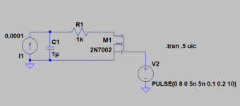
Decades ago I built a ramp generator with a 1mA CCS, and using the relationship
I=C dV/dt could measure C very accurately. (I think the circuit was from Popular Electronics). More recently, Microchip has a circuit diagram for a ramp generator using a depletion MOSFET (LND150) to effect the same thing.
Howdy folks,
Ive got a 95,000uF / 15V electrolytic cap that I suspect has gone off-value and I need to measure it. None of my meters can handle a value this large, so I need a technique. Heres what Ive got so far:
0.095F × 1000R = 95 seconds time constant.
I charge the cap to 15V, apply the resistor and start timing until the cap falls to 0.63 of Vo (9.45V), which takes around 90 sec. I take this to mean the cap is a bit down in value, but not bad - maybe 5% off?
But I dont think my procedure is right.. what are the correct numbers / calculations? Because when I charge this cap direct from a 15V supply (no resistor), it draws near zero surge current - and I'd expect quite a surge - like to the limit of the 1A supply.
Thanks.
The value needs to fall to 1/e of the original voltage, about 37%, for one time constant. The 63% figure is for charging up.
If the cap is empty it certainly should pull a big current from the 15V supply, unless it cuts out or is foldback limited.
There will be quite noticably dielectric absorbtion on a 90 second timescale, its better to measure the changes over a shorter timescale, both with and without a resistor so you can see if there's self-leakage or recovery. Also try a 100 ohm 2W resistor in place of the 1k.
The numbers aren't really adding up. First off this cap is marked 100,000uF @ 15WVDC not 95,000. The resistor measures 1020R giving a 102sec time constant. 0 37 × 15. = 5.5V.
Charging to 15V and applying the resistor, I get:
135s (1.33T) from 15V to 5.5V or
7.2V @ 102s
This indicates a capacity around 33% above the marked value. I've seen caps tolerance marked for +25% but this one isn't marked for tol. just value & voltage. It's also marked CDE which I take to be Cornell Dublier.
What to make of it?
Commercial capacitor manufacturers use a sourcementer to inject a fixed known current, dv/dt = I / C, you have to be able to measure dv/dt accurately.
So you're saying this is down to my measurement technique? Which aspect(s)?
Both dv and dt are so large that they are easy to measure within 1-2%.
Resistor value is read with an accurate 4.5 digit DVM.
Euler's number isn't subject to change.
Manufacturers may use a different technique, but this is a matter of practicality - they don't have a couple minutes per piece to test every cap. What am I overlooking? I'lladmit to being a bit of a novice metrologist, but I don't see where the error is creeping in.
Last edited:
In all my decades of servicing electronics, I've never come across something that uses 95K of capacitance.
What does this cap belong to?
What does this cap belong to?
In all my decades of servicing electronics, I've never come across something that uses 95K of capacitance.
What does this cap belong to?
It's not a piece of audio gear - it's actually one of those things that high-value, 3" computer-grade caps were designed for..
It's a computer. 🙂 an Altair 8800B, ca. 1977. They use linear power supplies, believe it or not. This cap filters the main 8V rail which is fed to the backplane and regulated down to 5V on a per-device basis.
Manufacturers may use a different technique, but this is a matter of practicality - they don't have a couple minutes per piece to test every cap. What am I overlooking? I'lladmit to being a bit of a novice metrologist, but I don't see where the error is creeping in.
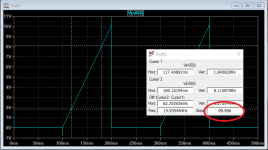
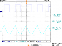
You use a constant current source of known value and measure the slope. A two transistor ccs would be accurate enough, a depletion mosfet better. Below 100uA CCS and 1uF capacitor discharged by 2N7002, slope is 99.996. You should be able to do this with any scope, but for a larger cap change the current (and use a beefier mosfet)
Attachments
In all my decades of servicing electronics, I've never come across something that uses 95K of capacitance.
What does this cap belong to?
We are talking 95mF, not 95kF ! Lets not go down the route of kµF, that way insanity lurks!
We are talking 95mF, not 95kF ! Lets not go down the route of kµF, that way insanity lurks!
OP = "Ive got a 95,000uF / 15V electrolytic cap......."
Can you use a capacitor within the meter measuring range in series to the 95,000uF cap and measure the total capacitance, then calculate the actual value of the 95,000uF cap?
C total = (C1*C2) / (C1+C2)
C total = (C1*C2) / (C1+C2)
Last edited:
In all my decades of servicing electronics, I've never come across something that uses 95K of capacitance.
What does this cap belong to?
Also common in high current battery chargers.
Also common in high current battery chargers.
Since my employment focus is in consumer audio/video products, that's why I never saw any 95K caps.
The cap is marked 100,000uF aka 100mF (milli-Farad) or 0.10F (1/10th Farad). It's 3" diameter × 5" tall. 95,000uF was my error, corrected in a previous post.
That's an interesting idea, but you'd need to have the value of the smaller cap to a fairly high degree of precision - and I suspect ESR may interfere as well. If I have time, Ill try it.
This also reminded me that I have a Heath IT-28 around here. Running that in EXT STD mode would be another potential way to measure it.
More than one way to skin a cap.. ugh.
Can you use a capacitor within the meter measuring range in series to the 95,000uF cap and measure the total capacitance, then calculate the actual value of the 95,000uF cap?
C total = (C1*C2) / (C1+C2)
That's an interesting idea, but you'd need to have the value of the smaller cap to a fairly high degree of precision - and I suspect ESR may interfere as well. If I have time, Ill try it.
This also reminded me that I have a Heath IT-28 around here. Running that in EXT STD mode would be another potential way to measure it.
More than one way to skin a cap.. ugh.
Well … legendre, your measurement technique is just fine. Fine-measuring the value of the draining resistor (1020 Ω) improves your accuracy. Choosing 0.37 × 15 = 5.5 V as the 'stop-the-timer' point is also good.
So, 135 seconds. = RC … 135 ÷ 1020 = C … 0.132 F … 132,000 µF.
The capacitor is marked '100,000 µF'. It is very, very common for power-supply capacitors (which undoubtedly, this is, right?) are +40% ÷ –15% tested. Also, over time, electrolytic capacitors' values will change, usually toward the lower side … because the diëlectric thickness ever-so-slowly gets thicker. Gives them better voltage tolerance too.
Hence why new-and-nearly-new ones can have such large over-printed-number values. Manufacturer is giving the consumer a big up-front bonus, knowing that over years of service, the nominal value will decrease … to still be within the printed value on the part.
So, ask yourself the question: is the placement of this nice high-value capacitor at some spot in the circuit where its +35% value would be a problem?
I'm guessing not — but only you will tell.
⋅-⋅-⋅ Just saying, ⋅-⋅-⋅
⋅-=≡ GoatGuy ✓ ≡=-⋅
PS: To all the posters going down the rabbit-hole of various testing techniques calling for measuring slope, and constant current, please consider — in context of a simple technique — the perfectly workable '1,000 Ω resistor' and 1/e (1 / 2.71828 → 0.368) method outlined above. I've used it repeated in this life … because handy resistors I keep in stock, and by choosing an appropriate one, I can measure any capacitor trivially from 1 µF to 1 F. With a stopwatch. Sipping tea. Thinking about quasars, black holes and gluons. … Just saying …
Last edited:
- Home
- Amplifiers
- Solid State
- Measuring large value capacitors