I want to check voltage points for my Dynaco ST-70, since the bias value seems too high.
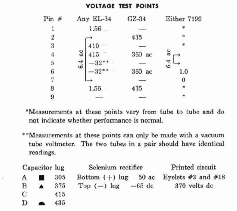
In the manual of the Dynaco ST-70, I found the attached voltage points for EL34, GZ-34, Capacitor lug, selenium rectifier (which I replaced with a diode) etc.
For example, EL34:
Pin 1 - 1.56v
Pin 2 - 6.4v ac
Pin 3 - 410v
Pin 4 - 415v
Pin 5 - 32**
Pin 6 - 32**
Pin 7 - 6.4v ac
Pin 8 - 1.56v
Pin 9 - --
The manual specify for ** "Measurements at these points can only be made with a vacuum tube voltmeter. The two tubes in a pair should have identical readings."
I am a newbie so few questions come to my mind:
Can I measure all these voltages with a common $10 digital multimeter?
I guess for each pin I'm testing the Red probe from the multimeter would plug into the pin. How about the Black probe? Should I always connect it to ground (which I suppose is the amplifier chassis)?
Your help understanding how to measure the pins will be very welcome and help me avoid being electrocuted
Attachments

DO NOT try to measure HV unless you are absolutely sure about what you are doing! To bias the ST70, you only need to measure pin 8, with the black probe connected to ground, it should read 1.56V. That's all...
Any decent modern DMM should have sufficiently high input impedance for this task. Back when the circuit was developed, only VTVM were good enough - ordinary multimeters had a much lower input impedance.
The black lead should go to circuit ground, which may be the same as the chassis. Be careful when measuring high voltages. My advice would be to avoid holding a probe tip on the point; instead use a test lead with croc clips so you don't have to hold anything while taking the measurement. Two reasons for this:
1. it keeps you well away from danger
2. it protects the equipment from accidental shorts when (not if!) the probe slips
Be aware that high voltage can stay on the equipment for a while after it has been switched off.
When I was training to be an Electronics Engineer with the Admiralty, the standard test meter was an AVO model 7. It had a 20kΩ/volt sensitivity. To measure HT multiply 20,000 by the voltage to work out the resistance of the load that the test meter will display. To a high impedance power supply, that is enough to skew the readings.
If you look at 80's amplifiers, the measurements take into consideration the load of the test meter.
Most quality DVMs have similar load resistance as VTVMs. In excess of 10MΩ/volt.
Beware when measuring high voltages as some DVMs will not handle more than 500V across the probes!
If you look at 80's amplifiers, the measurements take into consideration the load of the test meter.
Most quality DVMs have similar load resistance as VTVMs. In excess of 10MΩ/volt.
Beware when measuring high voltages as some DVMs will not handle more than 500V across the probes!
I tried measuring the input resistance of my DMM voltmeters.
Set one DMM to measure resistance and the other to measure voltage. Attached the probes to each other.
I got readings on most scales and for both DMM that showed ~10Mohms of resistance.
On the lowest voltage scales (199.9mVdc), this fell as low as 2.4M on a fairly new, very cheap DMM and to 293k on a very old DMM.
Do you think this method is valid? Does it give a reasonable approximation for input impedance?
Yes, that sounds OK. Useful to know that some cheap DMM don't do the usual 10M on all voltage ranges.
I'm somewhat worried that:
a) you don't know how to use a multimeter
b) your typed voltage table is wrong and you didn't notice it, which also casts doubts.
a) on pins 5 and 6 you have minus 32V or 32V negative , relative to chassis.
b) on pins 2 and 7 you do not "have 6.4VAC" but with one probe on one, the othar probe on the other, shown on the drawing, you measure 6.4VAC ; this is not a voltage relative to ground.
Sorry but I wouldn't suggest you mess with that amp guts until you learn a little bit more about measuring and multimeter use. 🙂
Just trying to keep you sound and safe so you continue with this wonderful hobby 🙂
a) you don't know how to use a multimeter
b) your typed voltage table is wrong and you didn't notice it, which also casts doubts.
the scanned voltage chart is right, of course, but you didn't copy it properly.For example, EL34:
Pin 1 - 1.56v
Pin 2 - 6.4v ac NO
Pin 3 - 410v DANGER
Pin 4 - 415v DANGER
Pin 5 - 32** NO
Pin 6 - 32** NO
Pin 7 - 6.4v ac NO
Pin 8 - 1.56v
Pin 9 - --
a) on pins 5 and 6 you have minus 32V or 32V negative , relative to chassis.
b) on pins 2 and 7 you do not "have 6.4VAC" but with one probe on one, the othar probe on the other, shown on the drawing, you measure 6.4VAC ; this is not a voltage relative to ground.
Sorry but I wouldn't suggest you mess with that amp guts until you learn a little bit more about measuring and multimeter use. 🙂
Just trying to keep you sound and safe so you continue with this wonderful hobby 🙂
I'll just throw my pennies worth in which might help you understand this 'loading' thing.
The old analogue meters used way back relied on taking a small amount of electrical current from the circuit you were measuring in order to actually work. This current, as small as it was, would not affect a voltage reading too much if the source impedance was low. But when you start measuring certain parts of tube circuits with their high impedances, then the error gets worse because of this loading effect. Valve/Tube voltmeters (VTVM's) and modern digital Multimeters have their own power supply so do not need to take their power from the circuit you are measuring. In the early days, manufacturers realizing that most people only had an analogue meter, would use the same to provide voltage check points in a circuit. When you are testing vintage electronics with a modern meter one has to take this into account as the specified voltages will always appear slightly lower than what you actually read on the meter.
The old analogue meters used way back relied on taking a small amount of electrical current from the circuit you were measuring in order to actually work. This current, as small as it was, would not affect a voltage reading too much if the source impedance was low. But when you start measuring certain parts of tube circuits with their high impedances, then the error gets worse because of this loading effect. Valve/Tube voltmeters (VTVM's) and modern digital Multimeters have their own power supply so do not need to take their power from the circuit you are measuring. In the early days, manufacturers realizing that most people only had an analogue meter, would use the same to provide voltage check points in a circuit. When you are testing vintage electronics with a modern meter one has to take this into account as the specified voltages will always appear slightly lower than what you actually read on the meter.
"Can I measure all these voltages with a common $10 digital multimeter?"
Perhaps you need to also identify the actual multimeter. Who knows, it may be only useful for automotive voltages, or you may try to measure voltage with the probes in the current terminals.
Even measuring bias current voltages would typically mean possible contact with HV circuitry, unless the amp had voltage sensing terminals available on the 'outside' that brought all voltages within selv (its a pity more amps don't do this for simple servicing, or people restoring old amps don't do this as part of the suite of changes made).
There is another reason why the vintage amplifiers read higher voltage
than the original specification and that's reading it with a Heathkit or RCA VTVM or my Fluke.
Back in the day when most of these vintage amps were made,the nominal AC voltage was between 110vac to 115vac on average. Today that goes as high as 125vac. Depending on where the manufacturer took the reading,you almost have to use a variac or tapped isolation transformer if you want to emulate the exact readings.
Chiming in:
There are a number of smaller DMMs with only 1meg input resistance. Conditionally, they may be used with a little arithmetic and Ohms Law, and a schematic of the D.U.T. Also as said, note the maximum DMM voltage input!
Good advice regarding mains voltage, often forgotten/ignored. Serious DIY-ers have Variacs; I use mine quite often when testing equipment.
Thanks to all that replied and pointed me in the right direction, or did let me notice some mistake in reading the Dynaco manual. I've managed to measure the voltages with the digital multimeter 🙂
- Status
- Not open for further replies.
- Home
- Design & Build
- Equipment & Tools
- Measuring "high impedance voltage" with digital multimeter