What is the measurement technique to determine how much DC a line matching transformer primary can reasonably take? I suspect I can get some DC with this unit because of appearances. I only need about 7ma and want to verify if I can see it take 8ma for some leeway. It is the 15K to 600R XSM line matcher from Edcor. I want to find out, via measurement, if it might replace a UTC A-25 or a Stancor WF-35 which appear to both withstand 8ma. It will be used at 180 volts.
What would be the technique to get this measurement? Maybe a Variac and ammeter to actually see the saturation curve? Or other method? If so how would I wire that up? Sorry but I'm learning here.
What would be the technique to get this measurement? Maybe a Variac and ammeter to actually see the saturation curve? Or other method? If so how would I wire that up? Sorry but I'm learning here.
I would connect it as a plate load for a 6922 or 6SN7 or similar tube. Put 100-200v on and use a bypassed variable cathode resistor. Load secondary with 1kohm or so.
Start a a low idle, 2mA perhaps, signal at grid for a decent swing on transformer output.
As u increase the idle current the waveform will eventually distort and become triangular at one side (the side that sees the max current).
Start a a low idle, 2mA perhaps, signal at grid for a decent swing on transformer output.
As u increase the idle current the waveform will eventually distort and become triangular at one side (the side that sees the max current).
Oh btw Ive used those in SE before and when using the entire primary where one end is at b+ (signal ground) the frequency response is quite bad. The part of the primary winding that is not swinging b/c it is to signal gnd capacitively loads the transformer/tube too much.
I ended up using only one of the primary windings and live with the lower inductance.
I ended up using only one of the primary windings and live with the lower inductance.
Oh btw Ive used those in SE before and when using the entire primary where one end is at b+ (signal ground) the frequency response is quite bad. The part of the primary winding that is not swinging b/c it is to signal gnd capacitively loads the transformer/tube too much.
I ended up using only one of the primary windings and live with the lower inductance.
Thanks SemperFi, I'm looking to use the Edcor secondary into high impedance. Basically as a transformer output preamp. I'll try to get through doing it this way. I have a bunch of different rheostats.
A classic simple approach is to drive a fullwave rectifier with variable AC, and load it with a resistor in series with the Device Under Test. The voltages and currents can be used to deduce the inductance (too much algebra for details in a post!). At low excitation, the inductance is more or less constant, at higher excitation the inductance falls. I've found that when it is down by 20% you've hit the limit on DC current.
In my experience with small line transformers, you can get about 1mA before the DC starts to saturate the core.
In my experience with small line transformers, you can get about 1mA before the DC starts to saturate the core.
Try driving it with a sine wave with a DC offset. Slowly increase the offset and watch for signs of saturation on an oscilloscope.
Try driving it with a sine wave with a DC offset. Slowly increase the offset and watch for signs of saturation on an oscilloscope.
Thank H713, now that is simple enough for me! At the same time I can test a few transformers with published specs to see if the test method follows along within reason.
As Paul notes in #5, a simple test jig can be used to plot primary inductance for varying DC current level, and with a certain AC excitation, as per link:
https://dalmura.com.au/static/Choke%20measurement.pdf
https://dalmura.com.au/static/Choke%20measurement.pdf
As Paul notes in #5, a simple test jig can be used to plot primary inductance for varying DC current level, and with a certain AC excitation, as per link:
https://dalmura.com.au/static/Choke%20measurement.pdf
I quickly scanned your article and liked it a lot. Will come back to study it and apply it to chokes in my closet with unknown specs. Thanks for you work and posting it. Very helpful.
Moderator: Please delete this accidental duplicate posting.
Last edited:
DC may not be the only issue.
The transformer might have trouble with the 6 Hz canon on Telarc's recording of the 1812 Overture.
But then, most loudspeakers fold up long before 6 Hz too.
Just trying to bring a fresh look at the limits of most parts.
The transformer might have trouble with the 6 Hz canon on Telarc's recording of the 1812 Overture.
But then, most loudspeakers fold up long before 6 Hz too.
Just trying to bring a fresh look at the limits of most parts.
......
Moderator: Please delete this accidental duplicate posting.
Too late for this one, but for future, for everybody:
If you can still Edit your post you can Delete it.
They don't make it easy. (This is a good thing!)
Get into Edit Box. At bottom find "Delete". This opens more things to click. You have to deliberately click on the "Delete Message" dot. Then you should say "Reason". Then you have to click on "Delete this Message".
So four clicks to say "Yes I am sure I want to delete".
EDIT: in the Advanced Editor the Delete buttons are *above* the edit box.
"Reason": the Moderators may look at this (and the deleted message) if a thread is making trouble
 , to know if a deleted message added fuel to the fire
  . Obviously this thread should not attract Moderator attention. But just in case it blows-up later, leave a clue.
 Attachments
Last edited:
DC may not be the only issue. The transformer might have trouble with the 6 Hz canon on Telarc's recording of the 1812 Overture. But then, most loudspeakers fold up long before 6 Hz too. Just trying to bring a fresh look at the limits of most parts.
Yep...
Attachments
disco,
Great!
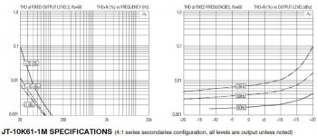
Works good at 20Hz @ 100mW referred to 600 Ohms (+20dBu), but only if driven from a 50 Ohm source.
What tube plate will be used that has an rp of 50 Ohms?
Lots and lots of negative feedback will lower the effective rp to 50 Ohms.
Is that a good way to use the transformer?
Great!
Works good at 20Hz @ 100mW referred to 600 Ohms (+20dBu), but only if driven from a 50 Ohm source.
What tube plate will be used that has an rp of 50 Ohms?
Lots and lots of negative feedback will lower the effective rp to 50 Ohms.
Is that a good way to use the transformer?
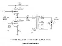
Not the best of ideas to drive a high impedance device to 50 ohms indeed. Jensen uses a cascode with 12BH7 so 4:1 would give reasonable amplification. Still, there's that large coupling capacitor so what is the advantage besides going balanced?
I played with the idea to replace the output cap with a real OT in my circuit to get rid of it. But, I wonder to what advantage as output impedance is already low and double numbers damping factor won't be that beneficial to drive a 10K solid state amp.
I played with the idea to replace the output cap with a real OT in my circuit to get rid of it. But, I wonder to what advantage as output impedance is already low and double numbers damping factor won't be that beneficial to drive a 10K solid state amp.
Attachments

Last edited:
- Home
- Amplifiers
- Tubes / Valves
- Measurement technique to determine max DC ma of line X former?