And finally, a picure of my measurement set-up, true DIY! 😀
You might get some reflections from the chairs but I wouldn't worry about that now. More important is to place the mike in the speaker's far field when measuring the system as a whole. 2m distance from mike to speaker is preferred. Make sure that there are no objects within 2m around the mike and around the speaker to prevent reflections. Is your space big enough for that?
Best, Markus
I hope that you will be doing polars of the drivers as well as the completed system. Otherwise just looking at axial data is not going to tell us very much.
I would do all the emasurements in the final enclosure with the tweeter in place. I would tend to do it midway between the two drivers, or maybe a little closer to the tweeter. Its not going to be too critical what you choos here unless you are too close.
Just so I have it straight in my own mind. Are you suggesting to take polars of the individual drivers separately and then the completed system with functioning crossover, or both the tweeter and woofer at the same time without crossover..?
If you're designing a speaker for use in 2pi space. How helpful are far field polar measurements at ~2M...? Or does the measurement procedure just need to include a reflective surface to represent what would be behind the speaker during normal use..?
Depending on the speaker baffle, the directivity of the DXT tweeter may usable even down to 1.5 kHZ, that's where I have a crossover with SB Acoustics 6".
Just so I have it straight in my own mind. Are you suggesting to take polars of the individual drivers separately and then the completed system with functioning crossover, or both the tweeter and woofer at the same time without crossover..?
If you're designing a speaker for use in 2pi space. How helpful are far field polar measurements at ~2M...? Or does the measurement procedure just need to include a reflective surface to represent what would be behind the speaker during normal use..?
If you are "designing" the speakers then you need the polars so as to determine how and where to cross-over. SO you need polars on each driver seperately. Then you "fit" a crossover to this data. Finally assemble the crossover and check to see that you got what you wanted.
I would do all measurements with the drivers in the both as they will be used in practice. Are these speakers going into a wall? Then measure them in the wall. If you can't do 2 m then do what you can, but remember that you will get some perturbations at the crossover from not being far enough away.
Be sure to gate the measurements. for 2 meters, about 6 msec.
Use HolmImpulse and gate out the first significant reflection. I can usuaully kill the floor bounce in my system with a huge stack of pillows. This is evident from the impulse response. But the ceiling is impossible to do anything about. Those two surfaces will virtually always limit you measurement capability.
We want that to be part of it.
It's speakers we're measuring, not drivers....
Of course, but when the microphone is so close to the speaker (like 2cm from the cone as shown in the picture) the response may be completely different than when the mic is 50cm away (a minimum typical listening distance). The way in which distributed cone radiation and distributed edge reflections add up at mic position should change at short distances.
I use to feel like the small child in The Emperor's New Clothes tale.
And now you feel like?
Eva. of course, this is true. Until you are several wavelengths away from a source, its response will vary with distance and angle simultaneously - near field. Once you are far enough away, then the response basically only varies with angle and 1/r falloff in magnitude - far field. In other words the r and theta responses are independent. Hence, measurements made in the near field do not represent what happens in the far field. Far field measurements are all consistant.
What I mean is that at some distance the mysterious dip between 700Hz and 1K may disappear or change.
Use HolmImpulse and gate out the first significant reflection. I can usuaully kill the floor bounce in my system with a huge stack of pillows. This is evident from the impulse response. But the ceiling is impossible to do anything about. Those two surfaces will virtually always limit you measurement capability.
HolmImpulse is an amazing program. Pure genius. I just wish my XP machine spoke English.
For some reason I can never kill the floor bounce completely. I've got to get more blankets and pillows.
DaVinci may have the answer to the ceiling. For some reason I don't think he'd say it was too much work.😎
Dan
For some reason I can never kill the floor bounce completely. I've got to get more blankets and pillows.
I don't think you can get rid of the floor bounces by a stack of pillows. I tried it and got very unreliable measurements. What happens is that you won't see sharp peaks in the ETC anymore but there's still a broad peak or dip in your data which gets easily confused with a nonexistent loudspeaker problem.
Best, Markus
Last edited:
I don't think you can get rid of the floor bounces by a stack of pillows. I tried it and got very unreliable measurements. What happens is that you won't see sharp peaks in the ETC anymore but there's still a broad peak or dip in your data which gets easily confused with a nonexistent loudspeaker problem.
Best, Markus
Actually I use a big block of foam and it works very well. Maybe not 100%, but 95%. That leaves maybe 1 dB of ripple possible. In my designs I shoot for 1 dB so this could still be an issue, except that I do even more to remove this reflection making it virtually gone.
Wow, looks like this is starting to generate some interest!
Thanks for all input and comments so far! 🙂
This thread is almost getting ahead of it self with regards to my initial purpose, so I hope y'all excuse me if I try to focus on the stepwise progress of establishing a good process.
Now, today; far field measurement:
I set everything up (see previous picture) and went to it.
Due to space constraints, I do not have the luxury of 2 meters free space in either direction. This is ultimately limited by floor-to-ceiling distance anyway, and with my kitchen-chair-cutting-board-and-grandma's-porcelain-painting-turntable set-up, the speakers end up roughly halfway between floor and ceiling.
In summary, I have a free distance of about 120 cm to the nearest major surface or object in any direction.
I followed Dr. Geddes' advise and pointed the mic towards the area between the tweeter and the woofer.
The tweeter is installed by the way, what I'm after is the "as-buildt" response.
So, did this give me a measurement down to 344 Hz??
Lets look at the curves:
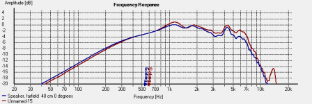
The blue curve is the straight measurement 40 cm from the speaker,with automatic gating at around 700 Hz.
I then measured from 90 cm to see if that would give any significant changes, not so.
The red curve is for the 90 cm measurement normalized to match the level of the first 40 cm measurement.
Well, that didn't take me down to 344 Hz.. something must have triggered the gate.. perhaps the chairs??
Thanks for all input and comments so far! 🙂
This thread is almost getting ahead of it self with regards to my initial purpose, so I hope y'all excuse me if I try to focus on the stepwise progress of establishing a good process.
Now, today; far field measurement:
I set everything up (see previous picture) and went to it.
Due to space constraints, I do not have the luxury of 2 meters free space in either direction. This is ultimately limited by floor-to-ceiling distance anyway, and with my kitchen-chair-cutting-board-and-grandma's-porcelain-painting-turntable set-up, the speakers end up roughly halfway between floor and ceiling.
In summary, I have a free distance of about 120 cm to the nearest major surface or object in any direction.
I followed Dr. Geddes' advise and pointed the mic towards the area between the tweeter and the woofer.
The tweeter is installed by the way, what I'm after is the "as-buildt" response.
So, did this give me a measurement down to 344 Hz??
Lets look at the curves:
The blue curve is the straight measurement 40 cm from the speaker,with automatic gating at around 700 Hz.
I then measured from 90 cm to see if that would give any significant changes, not so.
The red curve is for the 90 cm measurement normalized to match the level of the first 40 cm measurement.
Well, that didn't take me down to 344 Hz.. something must have triggered the gate.. perhaps the chairs??
Attachments
Last edited:
Now what to do??
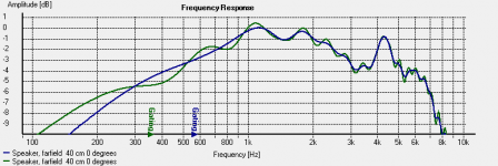
Well, I guess it's time to change the gating frequency and see if that can take me low enough without rendering the measurement completely rubbish.
Lets try for 350 Hz then..
Well, some ripple is obviously sneaking in, but it stays within 1 dB, which I guess I can live with as a happy amateur!
So, can we move on to splicing farfield and nearfield now??
Attachments
Hi Elbert,
This is very difficult to interpret below 1k. You have the typical baffle hump just above 1k, and below some dropoff d/t transition to 4pi space. Difficult to know exactly where because the effects of gating are starting to come into play.
Oversimplifying a bit, if the distance to first reflection is 3ms, the data becomes progressively less reliable as you approach 333 hz. First, the window alters the impulse and often affects the curve starting noticably an octave above, so the data up to 500-600 is just so-so. Can you post an actual impulse and the superimposed gate so we can look at what's going on in a bit more detail.
It's a useable curve if the intent is to design a straighforward xover. but you'd have to guess at bafflestep and model the low end.
I really like to go outside and get about 7-10ms of reflection free impulse response and measure from 2-3 m out. I know, that's asking a lot. But the measurements really are so much better.
Now what to do??
Well, I guess it's time to change the gating frequency and see if that can take me low enough without rendering the measurement completely rubbish.
Lets try for 350 Hz then..
Well, some ripple is obviously sneaking in, but it stays within 1 dB, which I guess I can live with as a happy amateur!
So, can we move on to splicing farfield and nearfield now??
Well, again, now you've got ripple and will have to guess at how much bafflestep to incorporate into the final design. It will be hard to get the bafflestep compensation very accurately. You may also have issues if you need a trap to smooth out the bafflestep hump since you don't know what's a real hump and what's ripple.
Again, I don't mean to harp, but 2-3ms is really not enough. I mean, I guess it depends on what your goal is. Going throught the trouble of using an Seas excel-can't you drag your measurement setup outside...?
All the real problems with measurements. I'm very lucky to have a room with 18 feet ceiling.
Now that would be nice. Outdoors is a hassle. Wind, rain. I mean, it works, but you definitely have weather related delays...
- Status
- Not open for further replies.
- Home
- Loudspeakers
- Multi-Way
- Measurement approach, 2-way closed box