Hi fellas, just me trying to DIY a Dallas Rangemaster.
Fuzz Central -- Dallas Rangemaster
I've got the OC71, the problem is the box is too small and I was thinking about a separate power supply. Now, I don't know if this is a good idea or not. A regulated 9 VDC? I s this going to make it noisier and, perhaps, not as good sounding? I have very little experience with stompboxes. What do you recommend? Any schematic?
Attachments
Last edited:
I've built tons of Rangemasters. They can sound good from regulated supply and it won't have any additional noise if there is enough filtering.
If you plan on using the external supply with that pedal only, it is OK with stick with the usual "positive ground" arrangement of the circuit. But, if you want to share the power supply with other pedals on a daisy chain, you will need to flip the circuit "upside-down" and wire it for negative ground, or else you will have trouble.
It is such a simple circuit, there are many opportunities for mods and variations to tailor it to your needs. I personally like adding a rotary switch to the input with a selection of different input caps, to give different tones. I usually start with a low value of around 2,2nF and progressively increase in size until about 47-100nF. At the higher values, it becomes a full-range boost with a fat dirty sound.
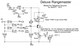
Here you go. This will work perfectly with both batteries and standard 9v supplies for pedals.
D1, R1, C1, and C5 work to decouple and filter the power line so that there should be no noise trouble and no problems with bad interaction with other pedals if used on a daisy chain.
It's good to include the trimmer for adjusting the bias, because it can vary from transistor to transistor and there is no one perfect value that will always work with all of them.
You will sometimes see people put these bias trimmers in other parts of the circuit. It is best to put it where it is here, in the place of the emitter resistor. This ensures that it will have a minimal effect on the frequency response as it is adjusted. Some people put the trimmer as part of the bias divider to the Base, but when you do that, the input impedance changes as the bias is adjusted, and this changes the tone because it changes the cutoff frequency of the high pass filter that is formed with the input cap. So... we put the trimmer on the Emitter, and we get a much more consistent circuit.
Another way to potentially power this circuit is to use a voltage inverter chip, like the TC1044, to derive a negative voltage from the positive supply. I've done this a few times and it works well, but it's an unnecessary complication for a circuit this simple, and can be a potential source of noise.
Attachments
Ok, I'm going to build the LM317 power supply and see how it goes.
https://www.smallbearelec.com/Projects/SmWart/SmWart.htm
As for the schematic, I like what you suggest because I really don't want a harsh, bright sound. The fat dirty sound is more to my liking.
https://www.smallbearelec.com/Projects/SmWart/SmWart.htm
As for the schematic, I like what you suggest because I really don't want a harsh, bright sound. The fat dirty sound is more to my liking.
We posted at the same time. Well, thank you very much for the schematic. It should take me a day or two to finish it. I'll post my impressions.
That supply should work well for it.
Rangemasters generally aren't that harsh sounding. Though they are naturally rather bright, it is a treble booster, they have a low input impedance that causes the some rolloff of the highs from the guitar's pickup. That's why it is important not to use a buffer in front of it. With the buffer, you won't get that natural high frequency rolloff and it will probably sound too harsh.
Rangemasters generally aren't that harsh sounding. Though they are naturally rather bright, it is a treble booster, they have a low input impedance that causes the some rolloff of the highs from the guitar's pickup. That's why it is important not to use a buffer in front of it. With the buffer, you won't get that natural high frequency rolloff and it will probably sound too harsh.
But if you use a large value input cap, like 47nF, it will be much fatter. That's why it's nice to have several on a switch for different tones.
Yeah, I'm going with the 47nF cap. No selector. Wiring it for negative ground makes it so much easier. I wonder why nobody seems to build it this way.
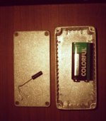
I have all the parts now. I hate to work with this small box, even the guitar jacks are too big.
I have all the parts now. I hate to work with this small box, even the guitar jacks are too big.
I've been able to fit these into a 1590A before, so you should be able to make it fit without the battery. Probably have to offset the jacks.
You could probably point-to-point wire it. Use the DC jack, footswitch, and volume control as tie points.
You could probably point-to-point wire it. Use the DC jack, footswitch, and volume control as tie points.
I will fit everything inside but not with the jacks I had. Standard jacks no good for this box. Too wide. Using special ones.You will see. I think it will be finished today.
I have a dilemma.
I have decided to use an external battery pack. I think it gives me more freedom and I don't have to worry about hum issues. My dilemma is the following: six Ni-Cad 1.2V batteries (2400 mAh) in series gives me 8 volts, I know it should be less but that's what I'm reading. It goes to more than 11 volts with eight batteries in series. I'd prefer six as the battery pack would be lighter. What would you do, iaxxaxxai? Is this circuit very sensitive to over/undervoltage?
* Seven would be ideal, I know, but due to the way I'm doing it, it's got to be six or 8.
Last edited:
It should work fine on 8v. You can adjust the bias if you need to.
I have actually built a pedal with an external rechargeable battery before. It was a pack of six cells. I don't remember the voltages it produced, it's been awhile.
You could use a standard 5,1mm barrel connector for the battery pack so the pedal could use either the batteries or an external supply. And then you could potentially use the batteries to power other pedals as well.
Great. It's six then.
Yes, that's a good idea. I thought about that. Thanks for everything. The circuit is finished but I haven't had the time to finish the box.
You could use a standard 5,1mm barrel connector for the battery pack so the pedal could use either the batteries or an external supply. And then you could potentially use the batteries to power other pedals as well.
Yes, that's a good idea. I thought about that. Thanks for everything. The circuit is finished but I haven't had the time to finish the box.
Funny, I just read the voltage - it's going down after the recharge. Probably it will stay on 7.2 volts. I think that would be too low. 8 cells then?
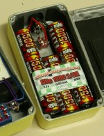
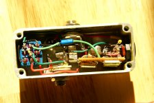
Here are pics. Also found a pic of that very small one I built awhile ago. It looks like there's extra stuff in the circuit for this one. Pretty sure I built it with one of those charge pump chips to make a negative supply. I don't do that anymore. LOL
Attachments
- Home
- Live Sound
- Instruments and Amps
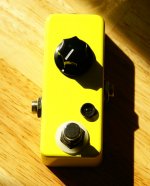
- **** me, I bought the wrong box.