@tamerlano
thank you for your interest in MDD projects.
A couple of years ago I tried to make some recordings with an H2n with old projects (665g and 669g), you can see them at: claudio gandolfi - YouTube.
I gave up for the bad result. Even if I learned to make quality recordings, there is a fact that thwarts the possibility of realistic listening to the recorded songs. Most loudspeakers try to simulate a point source. MDD projects were born as a linear source and in the latest prototypes also 3D. In addition to the height, I try to distribute the sound sources even in depth. For me, it makes no sense to evaluate the reproduction with a point origin of a sound created to have emissions with increasing delays in different points of space.
For the moment, the MDD technology remains exclusive and reserved for experimenters. About a year after the publication of the 34c9 project I have news of only two replicas:
- 34C9 project built by Pelanj
- projects 22C7.V2 and 22D7 (modified) built by Kec
You can read their comments and / or try to make a prototype, MDD projects are cheap and simple to build.
@ claudiogan
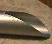
a pipe cut of the final part of the pipe made like the one in the picture, with the pipes all oriented in the same cutting direction could create a more directional sound and eliminate part of the divisions created by the walls if placed close to them?
Sorry for the bad English, I do better with Italian😉
Attachments
@tamerlano
according to Huygens' principle, each point of a wave front is the origin of a spherical wave front. To send the diffraction emission mainly in one direction, even a simple line with a length greater than the wavelength to be oriented can be effective.
In my MDD prototypes I assume that they are omnidirectional, I have not yet measured the emission with a polar graph. A cut like the one in the photo for now would only be a constructive complication. Now I am thinking of alternative geometries that make the appearance of MDD prototypes more conventional without the use of commercial tubes, at the same time I would like to have more freedom of choice in the measurements of the dimensions of the waveguides. It could take a long time, months.
I am unable to judge your English, my English is definitely worse. On the forum, I can communicate using automatic translation programs like Google Translator.
Just a note - this kind of slot is bending the sound waves of different frequencies at different angles. You can see some 3D simulations here: https://www.diyaudio.com/forums/mul...tube-1-compression-drivers-4.html#post6047971
MDD3A89. A complex double acoustic load
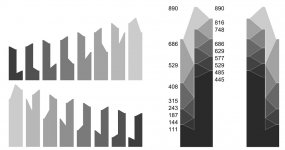
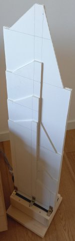
The acoustic load of the mdd3a89 project is complex. 300 waveguides of different lengths divide the emission of the full-range drive and by acoustic diffraction generate delayed and coherent spherical wave fronts in different points of space.
The mdd3a89 project is simple to carry out, a couple of days of work. It requires less effort than projects with rigid PVC waveguides.
The mdd3a89 project is inexpensive under 100 euros for material including a pair of 3fe25 drivers from Faital-Pro.
In MDD (Multi Delays Diffraction) projects, multiple, coherent and delayed emissions aim to mask unwanted effects of listening room reflections. A path difference between two reflections of a couple of meters corresponds to a delay of about 6 milliseconds, which may be sufficient to activate the precedence effect studied by Haas. For different frequencies of the same instrument, reflections from different points could be perceived, listening can be tiring due to the need to trace different sounds to the same origin.
The waveguides of the mdd3a89 project generate delays between 0.3 and 2.6 milliseconds, the envelope of the emissions expands (it lasts longer at the listening point) and the reflections are perceived as being generated by the same origin, the fatigue of listening decreases and sound recognition is easier. Omnidirectional emission with the multiplication of possible paths and further reduces the possibility of activating the precedence effect.
The 300 waveguides are distributed between front acoustic load (MDDFL) and rear acoustic load (MDDBL).
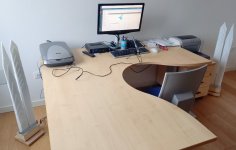
The wave guides are obtained by gluing 8 appropriately shaped 5 mm alveolar polypropylene panels. In the same panel, about 20 wave guides are obtained for the front acoustic load and 20 wave guides for the rear acoustic load. The alveolar polypropylene panels are elastic and light, they can vibrate by interacting with the sound waves reflected by the walls of the room. To reduce the phenomenon I have placed the loudspeakers at a distance of 60 cm from the wall and with the panels inclined by about 45 degrees.
The length of 890 mm determines the maximum delay of 3 milliseconds. By extending the lengths proportionally, the delay interval increases, strengthening the MDD effect, and the frequency response also extends downwards.
How does it sound? Best of all previous MDD projects. Compared to the 34c9 with similar dimensions the frequency responses and distortion measurements are similar but I definitely prefer it.
Anyone wishing to build a pair of MDD3A89s should not forget an adequate running-in. I used a pair of 3FE25s purchased in 2018 and stored in the box for two years. In the first two days the high frequencies were reproduced considerably attenuated. Now after about ten days the sound quality seems to continue to improve or maybe I am getting used to the sound.
Link:
Claudio Gandolfi - MDD (Multi Delays Diffraction Loudspeaker)
MDD3A89
The acoustic load of the mdd3a89 project is complex. 300 waveguides of different lengths divide the emission of the full-range drive and by acoustic diffraction generate delayed and coherent spherical wave fronts in different points of space.
The mdd3a89 project is simple to carry out, a couple of days of work. It requires less effort than projects with rigid PVC waveguides.
The mdd3a89 project is inexpensive under 100 euros for material including a pair of 3fe25 drivers from Faital-Pro.
In MDD (Multi Delays Diffraction) projects, multiple, coherent and delayed emissions aim to mask unwanted effects of listening room reflections. A path difference between two reflections of a couple of meters corresponds to a delay of about 6 milliseconds, which may be sufficient to activate the precedence effect studied by Haas. For different frequencies of the same instrument, reflections from different points could be perceived, listening can be tiring due to the need to trace different sounds to the same origin.
The waveguides of the mdd3a89 project generate delays between 0.3 and 2.6 milliseconds, the envelope of the emissions expands (it lasts longer at the listening point) and the reflections are perceived as being generated by the same origin, the fatigue of listening decreases and sound recognition is easier. Omnidirectional emission with the multiplication of possible paths and further reduces the possibility of activating the precedence effect.
The 300 waveguides are distributed between front acoustic load (MDDFL) and rear acoustic load (MDDBL).
The wave guides are obtained by gluing 8 appropriately shaped 5 mm alveolar polypropylene panels. In the same panel, about 20 wave guides are obtained for the front acoustic load and 20 wave guides for the rear acoustic load. The alveolar polypropylene panels are elastic and light, they can vibrate by interacting with the sound waves reflected by the walls of the room. To reduce the phenomenon I have placed the loudspeakers at a distance of 60 cm from the wall and with the panels inclined by about 45 degrees.
The length of 890 mm determines the maximum delay of 3 milliseconds. By extending the lengths proportionally, the delay interval increases, strengthening the MDD effect, and the frequency response also extends downwards.
How does it sound? Best of all previous MDD projects. Compared to the 34c9 with similar dimensions the frequency responses and distortion measurements are similar but I definitely prefer it.
Anyone wishing to build a pair of MDD3A89s should not forget an adequate running-in. I used a pair of 3FE25s purchased in 2018 and stored in the box for two years. In the first two days the high frequencies were reproduced considerably attenuated. Now after about ten days the sound quality seems to continue to improve or maybe I am getting used to the sound.
Link:
Claudio Gandolfi - MDD (Multi Delays Diffraction Loudspeaker)
MDD3A89
Attachments
Wow? That sounds like another project I would like to try out. And if it is better than 34c9, then I am all in. So now it is on my list, although a bit low since there are still many unfinished projects - like 34c9 V2🙂
Long times are also a common feature in the development of my MDD prototypes. While waiting, you may be able to choose between further variants.
I am curious to see the complete 34c9 V2.
I am curious to see the complete 34c9 V2.
Very curious about what kind of presentation the MDD speakers present.
How do they handle dynamics? I’m familiar with the faital 3fe22 and their capabilities and wonder if the mdd lens is a disadvantage vs direct radiating 3fe22/25 driver regarding dynamics and ”slam”? If you have an opinion regarding differenses
How do they handle dynamics? I’m familiar with the faital 3fe22 and their capabilities and wonder if the mdd lens is a disadvantage vs direct radiating 3fe22/25 driver regarding dynamics and ”slam”? If you have an opinion regarding differenses
From 2009 to 2013 I used JB3 direct radiation loudspeakers which were much more expensive than the T-Amp DAC I wanted to use at school for a liquid music practice. I tried to make a TL with cheap components.
One of the first attempts made was integra001, a TL prototype that did the opposite of the normal recommendations used on DIY sites. The waveguide in cardboard about one meter long vibrated throughout its length, the bass was reduced but despite this I preferred my prototype to the JB3, they had some other flaws. I have attributed my preference to the presence of secondary waves which facilitate the recognition of sounds.
In the last few prototypes I was able to extend the bass response while also improving the perception of details.
The closure of the driver in the MDD3A89 prototype is apparent. The front acoustic load has a total section at the entrance of about 26 cm2. The rear acoustic load has a total section at the entrance of about 32 cm2. They are not very different from a TL or horn configuration. In the path inside the waveguides, the losses are minimal, I do not use damping material, only air. At the exit of each wave guide, the diffraction phenomenon is exploited without appreciable losses.
In the MDD3FE25a prototype part of the direct emission of the 3FE25 was sent to the listening room, I did not detect any loss of efficiency by switching to the closed front acoustic load of the MDD3FE25d prototype. The closed and elongated front load greatly increased the perception of details, even of the lower frequencies reproduced.
With the MDD3A89 prototype I even have the problem of keeping them detached from the back wall, in some tracks the bass notes resonate with the room and are too prominent.
I am convinced that the latest prototype MDD3A89 is great for appreciating the excellent qualities of the Faital-Pro 3FE25 driver.
Attachments

Very interesting. I had a pair of tabaq’s with the faital 3fe22 a few years ago and found the lower end freq to be kind of one note bass lines quality. Your MDD lenses improve the articulation in the lows it seems then.
Why have you settlet on 3” driver? Could’nt the same (as you use for the 3fe25) MDD lens be loaded with a larger more dynamic capable driver (think 6”~8” coaxial driver or fullrange driver). Why do you strive to match the cone area to the opening area of the MDD mens? I’ve seen that danley soundlabs studio speaker has tiny ”slots” or holes in front of their midbass driver and it does not seem to degrade the fidelity. They use tiny slots for other reasons then the MDD is achieving.
Sorry for all the questions, trying to learn hos this thing work.
Edit: the danley studio use the slots minimize the distance betwene tweeter and midbass drivers but allso to improve dynamics compared to the small drive units they would need to use to achiev the same spacing with non slot loaded drivers. At least that is how I understod their reasons to it)
Last edited:
Your questions are helpful. I too am doing tests to better understand how MDD technology works.
I am using 3” drivers for two reasons:
- I have a certain number to make several prototypes at the same time,
- building prototypes for bigger drivers is much more demanding, often the work done is not reusable.
I made only one prototype (MDDHX135) with a 5” Ciare HX135. For now I use the rule that the total section of the waveguides is similar to the surface of the cone and to glue all the spiral sheaths I had to go outdoors on a terrace. When I have clarified my ideas on this new configuration I will move on to larger drivers. In the tests made with the HX135 driver, the difference in the displaced air volume is felt.
MDD technology can improve bass articulation as the different lengths are distributed over an octave Lmax = 2 Lmin. In standard TLs there is only one resonant frequency to adapt to the characteristics of the driver. With the lengths distributed evenly for each frequency between f(Lmax) and f(Lmin) there will always be a path of suitable length to transfer the acoustic energy from the compression chamber to the listening environment. Neutral cabinet.
In reference to the previous post on the loss of efficiency, I remember that I found the effect using guides of two meters or more. I believe the cause is due to the fact that the additional mass of the air confined in the wave guide is added to the mass of the cone and lowers the efficiency of the driver.
The term lens is not suitable for describing how MDD technology works. Optical lenses work with refraction. The light rays are deflected according to the focal points and the image is enlarged or reduced.... lenses ...
MDD prototypes use diffraction. The sound front is not deflected, it is divided and sent inside independent waveguides, after a few milliseconds, according to the Huygens principle each guide generates a spherical wave front. There is no focal point, there is a multiplicity of sound images. Individually they have a reduced quality but in the listener's brain they are recomposed like the brushstrokes of an impressionist painter.
The judgment on the result is subjective, clearly I like it.
Returning to a parallel with optics, I would refer to polarized lenses, they alter the chromatic scale of the image but eliminate the most annoying reflections. They are not ideal for a coachbuilder who needs to repaint a car, but they are used by the majority of people who want to enjoy a day at the beach.
Excelent clarification, appriciate that you take your time to share your knowledge.
Following this thread with much interest.
Following this thread with much interest.
@Couliogan:
I can imagine that the MDD sound fantastic with classical (concert hall) music. But does it sound good on modern music and rock? I’m thinking (without knowing) that diffuse omni sound is good for classical music but will sound a bit weird/defuse and unnatural with more modern music. What is your opinion?
I can imagine that the MDD sound fantastic with classical (concert hall) music. But does it sound good on modern music and rock? I’m thinking (without knowing) that diffuse omni sound is good for classical music but will sound a bit weird/defuse and unnatural with more modern music. What is your opinion?
Last edited:
Fantastic is a term I don't use. The reproduction of the latest prototype MDD3A89 is very good and can be further improved.
The difference to consider is between acoustic instruments and electronic instruments. For the acoustic instrument, there is a reference to try to approach, compatibly with the acoustics of the room in which the sound is reproduced.
For the electronic instrument, the situation has a further aspect linked to the artist's way of playing. You can have an ideal system in an acoustically perfect environment, but that doesn't necessarily have to be the condition in which the recording was made. Usually the artist has a medium quality amplifier available for his instrument, with a speaker that is almost never omnidirectional. Power and reliability are more important in a live performance. I expect that a rock song played in a Hi-End system, or with omnidirectional speakers, will not please the performer.
In the development of the various MDD prototypes I improved the detail, the frequency response and I did not worry about the maximum acoustic pressure. I mostly listen to jazz, pop and even rock music, more rarely classical, always at about 80 dB. I don't think the sound of the MDD prototypes appeals to a rock fan accustomed to listening at 100 dB.
The most "rock" of my projects is the latest MDD3A89, it has more bass than it seems from the frequency response I have published. The alveolar polypropylene panel I used is flexible, has a fairly large surface and interacts with the room's resonances. The sustained low notes are too prominent. It is the only MDD prototype that I have to carefully position at a certain distance from the walls. I am doing tests to eliminate this problem.
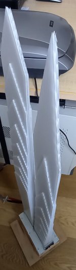
MDD3B89 another improvement in MDD technology
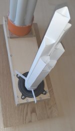
A further improvement over the mdd3a89 project with greater detail and ease of listening. It remains to pay attention to the positioning, excessive proximity to the wall highlights too much sustained low notes. The upper band should be slightly increased. I will not make any changes, I already have new configurations in mind.
The mdd3a89 project has the problem that the lateral forces applied to the alveolar polypropylene panel are not symmetrical, spurious vibrations are generated which can be detected in the reproduction. In the measure of the distortion I cannot highlight the effect, while listening it is evident. In the mdd3b89 project the front acoustic load is separated from the rear acoustic load. Both acoustic loads use 16 honeycomb polypropylene panels 2.5mm thick and shaped to tip. The tolerance of manual processing is about 1 mm, within this error all lateral forces are considerably reduced compared to the mdd3a89 prototype in which there were differences of several cm per project.
Link:
Claudio Gandolfi - MDD (Multi Delays Diffraction Loudspeaker)
MDD3A89
MDD3B89
Attachments
Last edited:
For 3FE25 rear waveguides extend range to 40Hz with 90dB sensitivity?
How much space does it take? What if we use 5FE120 - can we reasonably extend to 30Hz?
How much space does it take? What if we use 5FE120 - can we reasonably extend to 30Hz?
If I had these answers ready I would probably also be able to commercialize MDD technology.
Now I'm working with 5mm honeycomb polypropylene. Compared to the MDD3FE25d project the sound is more detailed even if there are no variations in the distortion graph. It could simply be the gluing of the guides with flat surfaces instead of circular ones that eliminates spurious vibrations. It could also be the timing of delays.
The lengths I have chosen and the configuration adopted in the MDD3A89 and MDD3B89 projects make the frequency response irregular, -10 dB between 3 and 10 KHz. When listening I have to keep the speakers away from the walls to prevent the bass from covering the rest. Despite the attenuation, I can hear more details even on the highs. With a little bit of testing, I should be able to regularize the frequency response while maintaining the current detail.
For the resonant frequency, the length of the waveguides in the rear acoustic load matters above all. In the MDD3FE25d project with a maximum length of 2 meters the first impedance maximum is at about 47 Hz. In the MDDHX135-42 project with a maximum length of over 3 meters and the first impedance maximum is at 33 Hz. In the MDD3A89 project with a maximum length of .89 meters the first impedance maximum is about 70 Hz.
I have not yet made sensitivity measurements but I believe that keeping the total surface of the guides similar to the area of the speaker cone there should be no significant losses.
For the 5FE120 driver I would do a test with the measurements of the MDDHX135 project, the rear load waveguides extended up to 4 meters and wrapped in a cubic box style subwoofer. To reproduce 30 Hz or less it is necessary to bend the waveguides one or more times, they must be longer than 2 meters.
The previous tips are for those who want to experiment, the result is not guaranteed.
I'm asking because with compression driver I can 60Hz with 100cm mouth hypex horn, length over 3 meters bent like C shape or like spiral. This leads to 105dB@2.83V and front side can be waveguide. Since you operate at Sd cross section then size is more compact. Compound loading as you do is interesting.
I didn't understand if you want to use a compression driver or a Faital-Pro 5FE120. In any case, a horn with an output section equal to the Sd of the 5FE120, 84 cm ^ 2 (90 x 90 mm approximately) can be used as an adapter.
All the prototypes I made are omnidirectional with an emission on a hemisphere centered on the floor. Do you want 105 db at 2.83V at one meter? With what angle of diffusion? A horn is directional so the nominal pressure is within an angle that depends on the geometry used in the construction.
If omnidirectional emission is fine, with the compression driver I would use a 90 x 90 mm front loading made with 10 mm honeycomb polypropylene and Lmax = 2 Lmin = 1500 mm. There is no rear issue.
With the 5FE120 driver I would use a 90 x 90 mm front loading made with 10 mm alveolar polypropylene and Lmax = 8 Lmin = 1000 mm, and a rear loading with Lmax = 2 Lmin = 1500 mm.
If I understand what you want to achieve, I can calculate the measurements of a test configuration to verify. Operation is not guaranteed. There are still things that I have not verified for the use of diffraction as a means of diffusing sound energy. Since September I have been doing tests with waveguides with a section of less than 10 mm only to discover that with a section of 5 mm the sound energy is considerably attenuated. Most of the time I used it to make a first mechanically stable prototype.
- Home
- Loudspeakers
- Planars & Exotics
- MDD Multi Delays Diffraction (Multi TL, omnidirectional, single drive, ...)