So the other day, out of the blue, I start thinking about some sales literature I read a few decades ago about McIntosh amplifiers. The paper went into some detail about why they chose to use output transformers on a solid state amplifier.
I’ve done a bit of poking around, here and elsewhere, and cant seem to come up with an explanation of what the thinking was.
I can think of two reasons for doing this, but neither seems to wholly justify what are some big beefy expensive transformers.
One thing the transformer would do is isolating the speakers from any DC offset.
Another issue would be insuring that the output transistors are always seeing the same load. I’m thinking this might have something to do with the answer as the transformers usually had taps to match the speakers’ impedance.
I had the use of a Mc250 for a while and found it a nice sounding amplifier.
Does anyone remember what the story on these things is or where I can find old McIntosh stuff online?
Thanks
autoformer?
A single winding x-fomer? Isnt that jus t an indictor?
I found this expalanation:
http://www.hometheaterhifi.com/volume_8_3/mcintosh-mc-602-power-amplifier-8-2001.html
But I still feel a bit puzzled.
- Dave
A single winding x-fomer? Isnt that jus t an indictor?
I found this expalanation:
http://www.hometheaterhifi.com/volume_8_3/mcintosh-mc-602-power-amplifier-8-2001.html
One thing that makes McIntosh amplifier designs very different from others is the use of output transformers. The photo below shows a top view of the MC-602. The front of the amplifier is to the right. The power toroidal is inside the rectangular metal case in the center, and the two output transformers are at the top and bottom. McIntosh calls them Autoformers™ because there is only one winding, so it really is not actually a transformer. With a conventional push-pull amplifier, the + leg and the - leg may not output exactly the same voltage on a waveform. So, when you drive the amplifier to its limits, the lower voltage let will give out first, and the other leg can drive its extra voltage back into the leg that gave out. This can damage the amplifier. The use of the autoformer maintains absolute balance of the two legs. Secondly, regardless of how unstable the speaker load, the output transistors never see that instability when the autoformer is used.
But I still feel a bit puzzled.
- Dave
"Secondly, regardless of how unstable the speaker load, the output transistors never see that instability when the autoformer is used."
WTF?
An autoformer is an impedance matching device. Pure and simple.
Loudspeakers are not unstable. Amplifiers are unstable.
WTF?
An autoformer is an impedance matching device. Pure and simple.
Loudspeakers are not unstable. Amplifiers are unstable.
Dave,
That has to be BS, I can you have a continuous transformer like and inductor. After all you have to have isolation of the primaries and secondary winding to form a transformer.
I have a number of MAC amps and somewhere around I have a diagram of one of their auto-formers. The principle is similar to that of a tube amp. Really that one of the problems with the MAC transistor gear is very low damping factor. When you compare it to a DC couple amp that don’t have the bass control till you get to their really big amps. I do think they have a smooth sound that is related to the transformer.
Yah,
I'm hoping that the quote is just a poor paraphrasing of something that Frank McIntosh wrote.
As written I don’t think the claims of isolation or protection from DC components to the audio waveform are justified.
I think I have gotten used to the idea of the single winding autotransformer. Its just like the one that most of us (but not me currently) have on our workbenches and sometimes call a variac.
While I find it easier to fathom a transformer providing protection from waveforms with DC components, I don’t see it as being a decent cure for not having enough bolas in the power supply.
-Dave
Step one: spell check
Step two: cut-n-pate
Step thee: post
I'm sure it is the same idea behind the "Zero Autoformer" that has been floating around in some high-end and DIY publications and sites that last couple of years. The Mac has binding posts for 8, 4, and 2 ohms. More substantial but otherwise just like a chintzyRadio Shack PA amp I recently gutted for it's enclosure. In the case of the PA amp I suspect it just lets the unit rdrave a number of parrallel speakers. In the case of the "Zero" I think it was dreamed up by a guy who couldn't drive Magnepans with his existing amp.
Possible advantages for the MAC could include limiting beta droop, controlling operation to a smaller part of the SOA which would let the amp drive a wider variety of speakers while makinf IV limiting easier.
Possible advantages for the MAC could include limiting beta droop, controlling operation to a smaller part of the SOA which would let the amp drive a wider variety of speakers while makinf IV limiting easier.
I thought the idea behind the autoformer were a number of reasons. Impedance control, keeping the amp stable under reactive loads, Mac claimed that it was an improved in sound. When Mac started this in their transistor amps, they dropped their tube gear line. Of course, they are selling tube stuff again but company has changed hands. Another claim was you were getting the stability ruggedness of transistor but with a similar sound to that of tube.
Anyway, the autoformer does worse the damping factor of an amp. If you have ever gone to a Mac clinic and ask them that question they would say tell up that was a bogus specification, I do not think so. Of course, their amps will still play low frequencies, however it lack the ability to control a speaker the way a large DC coupled amp does. In addition, I do not believe Frank McIntosh would have written that. When you get to their really big amps, I do not believe it really makes a difference.
🙂
Can you say SOA?
For the longest time McIntosh used ±35V~40V on all their amplifiers.
During this time frame 30V SOA parts were typical and it was just hard to find anything much above 50V. The most popular 2N5630/6030 were 200W/30V but only 63W/70V.
Bozak and Threshold had amplifiers with TRIPPLE series connected ouputs. Dynaco, SAE, GAS, SWTPC, Bryston, all used double series connections.
"A single winding x-fomer? Isnt that jus t an indictor?"
Yes, the autoformer is an inductor with taps. Unless you are driving a 200V line of ceiling speakers, galvanic isolation is not needed. This allows a 50% reduction in size, cost, etc., over a full transformer of the same power and bandwidth.
"Really that one of the problems with the MAC transistor gear is very low damping factor. When you compare it to a DC couple amp that don’t have the bass control till you get to their really big amps."
Damping factor is a red herring.
The trademark 'soft' sound McIntosh is known for comes from electrolytic caps in the signal path and no power supply bypass caps. Adding a pair of 47µF electrolytics to the main supply, and a few 0.1µF film caps to the signal path, was a revelation.
The McIntosh with $4 worth of caps added sounds cleaner and tighter in the bass than amplifiers having damping factors of 400 and up.
An 8 ohm loudspeaker typically has 6 ohms of DC resistance. How much does it matter that my amplifier has 0.5 ohm vs 0.005 ohm output impedance? The real damping to the loudspeaker back EMF is only 1.23:1 vs 1.33:1
Cost and weight are the real drawbacks for autoformers.
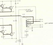
You right the autoformer is an inductor. I found an old schematic of a MC2505 amp I owned. Yep back then folks would give you a schematic of the amp you purchased at least Mac did.
With all that said, I have owned 6-7 Mac transistor amps. They are heavy and sound good for the time. Still the only their amp had a problem with damping it a fact of the design. Even though they had a issue with power control a low frequencies, not as good as a Crown DC300, it was a much better amp over all. Still if you are playing a pair of Klipsch horn are some A7 Altech’s or JBL studio monitors that was not real issue
With all that said, I have owned 6-7 Mac transistor amps. They are heavy and sound good for the time. Still the only their amp had a problem with damping it a fact of the design. Even though they had a issue with power control a low frequencies, not as good as a Crown DC300, it was a much better amp over all. Still if you are playing a pair of Klipsch horn are some A7 Altech’s or JBL studio monitors that was not real issue
Attachments
Nah,
Jewilson:
I didn’t think for a second that Frank McIntosh wrote that stuff. It does however have the feel of something that’s been through marketing and out to a magazine author. Perhaps it’s been McMarketeered?
DJK:
Interesting thoughts about the transistors of the day influencing the decision to use the auto-x-former. So is what your saying is that using the autotransformer for removing DC waveform components is because of the 35v rails instead of using parallel output devices at 70v? Likewise, is it the relatively low rail voltage that emphasizes the importance of matching the speaker impedance?
DJK/Sam9:
I dint really figure that the McInformer had anything to do with 70v or 25v line applications, although I think I see what your getting at about galvanic isolation. I suspect that the Radio shack amp had multi taps to allow for 70/25v line selection. I think these things used Hi-Z xfomers at the speakers to allow multiple speakers to be bridged onto the line without loading down the amplifier. Good for paging/narrowband applications. I’ve got an old Bogan downstairs waiting to parted out.
So what would the characteristic impedance of the autotransformer look like to the transistors and vice versa? Are they doing something like 600:600, 8:8, or .5:10k?
The other thing I’ve been wondering about is if there is a characteristic sound to the autotransformer itself? If its allowed to ring (just a little) could this be a pleasant coloration to the sound?
I’ve heard arguments about "good" vs. bad distortions... but that’s probably best for another thread.
Having my early career involved with repairing Mac equipment,
I think I can offer an educated guess.
I don't think reliability was an issue - the Mac output stages
were plenty beefy enough, and there were very few failures.
McIntosh was transitioning from tubes to SS, and their designers
were comfortable with transformers, which was part of it, but
also the transformer (or autoformer - same thing) has some of
the qualities of the older tube sound, and this smoothed the
transition for their customer base.
Damping? One listen to the early McIntosh speakers could
convince you that they weren't very concerned about those
issues. 😉
From the schematic I'm gonna guess that the amplifier has a 6 ohm impedance prior to the autotransformer.
Thanks for the schematic! It helps a lot.
An acquaintance who used to own a big PA company told me that what the DC-300 did for him was give him the ability to run 2 ohm bridged loads. I think I'm one of the few out there who hasn’t held onto my affection for the DC300. Last time I unpacked a new one I was sorely disappointed at the quality. It was such a "mature" product that it didn’t look like anyone paid attention or cared. Contrasted with a Bryston 4B at about the same money...
My experience with the Mc250 was mostly with some not so good A-7 clones built from some OK EV drivers. LF wasn’t much of an issue with those, but I'm also not too sure how accurate my memory would be of that.
I need to go do some real work for a while. I'll check back in tomorrow night.
-Dave
Thanks for your input Nelson. (I didn’t really want to go back to work anyways.)
Its that "tube sound" transition that always keeps me wondering. Was it merely the presence of the extra iron that made this a good marketing move or does it really have a pleasant coloring affect to the sound.
I read this article around, oh 1990, where the author was talking about why people really do like things with input transformers and vacume tubes. I wish I could remember the where and who. I think the assertion was made that distortion that truly occurs coincident the harmonic content of the waveform sounds pleasant. Now I’ve never been able to figure out an analogue method of building something that would follow an envelope and distort at a major 5th (a very pleasant interval) but it would seem that octaves are going to occur kind of naturally.
Nelson, I think I remember you saying that your AP gets parked next to your bed and night and follows you through the day, and yet I 'm pretty sure that you also advise people not get too hung up with distortion numbers.
So, form this I'm starting to feel a very limited usability of the THD+N reading (and I’ve always enjoyed hitting that button on the Tek 500 too).
I think this may be leading up to my trying some kind of output iron on one of the GC kits I have coming form BrianGT.
- Status
- Not open for further replies.
- Home
- Amplifiers
- Solid State
- McInformer?