Does anyone have schematics for this amp. Nothing stands out visually but I dont have a power or protection light so I assume their is a PS issue?
Tia
Tia
Post the DC voltage on all pins of the TL494 driver IC. Copy and paste the following and fill in the blanks.
Pin 1:
Pin 2:
Pin 3:
Pin 4:
Pin 5:
Pin 6:
Pin 7:
Pin 8:
Pin 9:
Pin 10:
Pin 11:
Pin 12:
Pin 13:
Pin 14:
Pin 15:
Pin 16:
Pin 1:
Pin 2:
Pin 3:
Pin 4:
Pin 5:
Pin 6:
Pin 7:
Pin 8:
Pin 9:
Pin 10:
Pin 11:
Pin 12:
Pin 13:
Pin 14:
Pin 15:
Pin 16:
Hi Perry
I removed the insulators try to get in there better. Then used a small battery versus a set supply like an idiot shorted two pins on the 494 and got the smoke from the power supply. Where do I go from here. i think what was minor I just made major.😱
I removed the insulators try to get in there better. Then used a small battery versus a set supply like an idiot shorted two pins on the 494 and got the smoke from the power supply. Where do I go from here. i think what was minor I just made major.😱
What smoked?
When testing, you should have a low-rated fuse (10 amp or so) in the B+ line or have an inline B+ limiter. It won't save the amp from all mistakes but it reduces the risk in case of one.
After the amp is powered up, you have to either monitor the temperature of all of the heatsink mounted components closely or have them clamped tightly to the heatsink.
I have the Z44N here so let me replace these and start over Q3 was fractured but I did this before there had been no sign or essence of tghe smoke anywhere the board was immaculate.Amplifier was certainly not abused. Just started acting intermittent then finally no power. But the fuses never blew and even on the bench no power 😱
Last edited:
Check the drive signal and the gate resistors before installing the FETs. The driver transistors and the gate resistors could have been damaged.


3205s are rarely OK to use with 100 ohm gate resistors unless deadtime is programmed into the drive circuit.
From ground to pins
Pin 1: 0 vdc
Pin 2: 0 vcd
Pin 3: 0 vcd
Pin 4: 0 vcd
Pin 5: 0 vcd
Pin 6: 0 vcd
Pin 7: 0 vcd
Pin 8: 13 vdc
Pin 9: 0 vcd
Pin 10:0 vcd
Pin 11: 0 vcd
Pin 12: 0 vcd
Pin 13:13 vdc
Pin 14: 0 vcd
Pin 15: 0 vcd
Pin 16: 0 vcd
Pin 1: 0 vdc
Pin 2: 0 vcd
Pin 3: 0 vcd
Pin 4: 0 vcd
Pin 5: 0 vcd
Pin 6: 0 vcd
Pin 7: 0 vcd
Pin 8: 13 vdc
Pin 9: 0 vcd
Pin 10:0 vcd
Pin 11: 0 vcd
Pin 12: 0 vcd
Pin 13:13 vdc
Pin 14: 0 vcd
Pin 15: 0 vcd
Pin 16: 0 vcd
Pin 12 needs to have 12v. Follow the circuit back to see where it's lost. There is likely a transistor between the remote terminal and pin 12 that's at fault, assuming that the transistor is being driven on by the remote.
Is it defective?
What was the voltage on it's terminals in the board?
It's odd to have an NPN transistor in that type of circuit but not impossible. Confirm that there is no PNP instead in that circuit. The NPN generally drives the PNP which drives voltage to the IC.
What was the voltage on it's terminals in the board?
It's odd to have an NPN transistor in that type of circuit but not impossible. Confirm that there is no PNP instead in that circuit. The NPN generally drives the PNP which drives voltage to the IC.
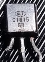
How about the a1015 almost 100 percent thats where it goes. I never checked the npn in board because there isnt alot of room to even seen what is written on the transistors.
I checked it with the multi meter and saw no OL across the base to emitter or collector and no voltage drop from the emitter or collector to the base
Last edited:
- Home
- General Interest
- Car Audio
- mb quart ONX4.60