Hi Sommer,
Can't see the page ,could you post some photos may be?
Thanks alot.
hello
is there a difference between them
besides 2 x and 4 x tda7294 tda
is there a difference between them
besides 2 x and 4 x tda7294 tda
Attachments

Last edited:
yes, they are very different.
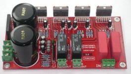
The red PCB is a pair of bridged channels and can only be used with 8ohm speakers.
The blue PCB is a pair of channels and can be used with 4ohm, or 6ohm, or 8ohm, or 4 to 8ohm speakers.
The Blue has UPC protection chip.
The blue has opamp input !
The red PCB is a pair of bridged channels and can only be used with 8ohm speakers.
The blue PCB is a pair of channels and can be used with 4ohm, or 6ohm, or 8ohm, or 4 to 8ohm speakers.
The Blue has UPC protection chip.
The blue has opamp input !
I see NE5532 on the PCB.
It can't be a DC servo, it's the wrong opamp for that.
It must be some input opamp.
It can't be a DC servo, it's the wrong opamp for that.
It must be some input opamp.
Last edited:
Why does the chipamp need an opamp to act as a buffer?
Because it's cool !
There are some equipped with a tube buffer .
I've read that the LM3886 does perform good with a 10/20 K pot at its input .
Not the same as for the LM3875 .
Of course I would bypass the IC buffer stage in that kit .
And I would start with a separate PSU for the tube one 😛
Hi Pico,
since you are the only one brave enough to stand up to the plate, could you tell me why you think a chipamp could benefit from a buffer at it's input?
since you are the only one brave enough to stand up to the plate, could you tell me why you think a chipamp could benefit from a buffer at it's input?
I was ironic BTW
If you put something more in a kit ,I'm sure the goal is to 'catch pigeons' .
That buffer could be anything ...who knows...a DSP correction 🙂
and someone may think that a 'buffer' may be a plus . But it only guarantees a high impedance load to the device attached .
Reading the 3886 DS it is clear that it was projected to have an 'high acceptance' input ,thus not needing any buffer . Some people have reported that using vacuum tube for that duty is much better .
but why a buffer at the input of a chipamp?
A buffer is usually there to drive the cable that feeds the receiver.
The tube buffer, or the opamp buffer, or the discrete SS buffer should be at the source end of the cable, not at the receive end.
A buffer is usually there to drive the cable that feeds the receiver.
The tube buffer, or the opamp buffer, or the discrete SS buffer should be at the source end of the cable, not at the receive end.
Wouldn't that be called a line driver?A buffer is usually there to drive the cable that feeds the receiver.
AndrewT
I think Buffer is added to cover losses in tone (Bass Treble)control stage.
I think Buffer is added to cover losses in tone (Bass Treble)control stage.
Last edited:
svsommer
I want to make a PCB for my TDA7293 IC pair so
help by Posting the poto of other side of the 2X PCB
Thanks !
I want to make a PCB for my TDA7293 IC pair so
help by Posting the poto of other side of the 2X PCB
Thanks !
svsommer
I want to make a PCB for my TDA7293 IC pair so
help by Posting the poto of other side of the 2X PCB
Thanks !
try this design TDA7293V
Sorry I dond have any PCB designs as your requirement right now. If I can manage to get that, I will definitely post it for you.DEAR diptangshu !
THANKS BUT I WANT PCB WITH SPEAKER PROTECTOR.
I THINK THIS IS BEST PCB.
- Status
- Not open for further replies.
- Home
- Amplifiers
- Chip Amps
- Maybe I should go for chip amp!