G.Kleinschmidt said:
Yeah, lets all pay attention to what Mr Colloms says.
The NFB in the amp goes round and round
Round and round
Round and round
The NFB in the amp goes round and round
All day long
Wavebourn said:
Looks like a nice microphone input.
I promised no more sarcasm
Bob Cordell said:
BS meter is pegged. Name-dropping is not a substitute for a technical comment.
Cheers,
Bob
Searching still shows no active applications or patents as of July 9 by any of the parties mentioned.
john curl said:Bob, I am looking to both Otala and Mitch Cotter. You didn't try hard enough.
Why keep looking to someone else. You should be able to explain it yourself since you are the one who is in disagreement.
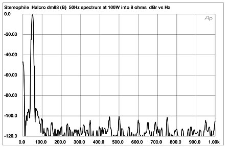
And here is the Halcro dm88 spectra at 50Hz, although in fairness it is not measured at the same power level as the JC-1.
regards
trev
Calling me a liar, Scott? I am not saying ANYTHING about what I once referred to. I am working with Michael Cotter, now. I will rely on his input as Matti apparently did, decades ago. We have seen PIM on the screen, and we now know that it can be measured effectively. Why it is so important sonically is now the REAL question. Scott, I have never knowingly lied on this or any other website. What would be the point? To be found out, in future? To sell some sort of gizmo? Please, be civil, and I will return the civility. You may not agree with me on what is IMPORTANT in audio design, that is understandable, but I am pretty darn successful, sonically, in my own right, especially when I avoid IC's if I can, and only use the 'best' when I can't.
100W Trevor, 100W, into 8 ohms. Measure the JC-1 at 100W too! What is wrong with you, can't you read a graph?
SY, I just tried to call you on your new number. No luck. No, SY, they are looking for new feedback or PIM Patents and they can't find them, if I am not mistaken.
Now, it might be Mike's patent, and it might be my other friend's patent. Well, I don't find it either useful or productive for my associates, to give out further info at this time. I'll show you Mike's patent (distortion and noise), if you won't blab it over the universe, if you want to see it. It is up to you. I don't like the idea of big company lawyers looking over patents (especially pending), who would love to find something to complain about. Please don't tell me that I am paranoid, or I will be forced to bring out each and every time I have shared over the last 40 years, and been cheated, even to the point of taking my idea, drawn on a napkin, and trying to patent it themselves.
Now, it might be Mike's patent, and it might be my other friend's patent. Well, I don't find it either useful or productive for my associates, to give out further info at this time. I'll show you Mike's patent (distortion and noise), if you won't blab it over the universe, if you want to see it. It is up to you. I don't like the idea of big company lawyers looking over patents (especially pending), who would love to find something to complain about. Please don't tell me that I am paranoid, or I will be forced to bring out each and every time I have shared over the last 40 years, and been cheated, even to the point of taking my idea, drawn on a napkin, and trying to patent it themselves.
Sorry, my son was using the phone. I'll call you tomorrow.
Patents are public documents- anyone can see them. Even applications after (I thinK 12 or 18 months. During the examination process, anyone can see the correspondence between the PTO and the inventor, the building of the so-called file wrapper.
I'd be very interested in seeing that one- at your encouragement, I read through Bruce Candy's patents and they were indeed very educational.
Hi BobBob Cordell said:
"Cordell's PIM measurement method" is a direct hardware implementation of Otala's prescribed method of PIM measurement, so if you have a problem with it, you need to look to Otala.
Bob
I looked your project on your site, even using very negative feedback, you reduced all the distortions in open-loop.
I have noticed that those who built your amp like the sound. Probably that true that not is need low feedback and further open-loop.
I have noticed most other projects which have very distortions in open-loop, differential pair (BJTs) without degeneration, low input resistance of the output stage, these two examples are well known as a source of distortion in open-loop. But high negative feedback "hide" this distortion or "mislead" the TDH meter, as I have heard talk...
I wonder if the high distortion in open-loop would be detected by measures PIM?
SY said:
No, he just said you were mistaken.
Actually I just wanted to read the stuff since it's public anyway. I simply said I can't find it with sketchy information. This kind of stuff would seem a perfect candidate for trade secret rather than patent, it's the method of choice with exotic trim and test techniques.
OK joke break (this is real),
Postdistortion amplifier with predistorted postdistortion
Abstract
A postdistortion amplifier that produces a postdistortion amplifier output signal based on a signal input to the postdistortion amplifier reduces distortion in the postdistortion amplifier output signal by digitally predistorting an error signal. The postdistortion amplifier includes a digital predistortion unit that receives a digital error signal and produces a digital predistorted error signal based on the received digital error signal and by reference to a predistorted error signal model.

john curl said:100W Trevor, 100W, into 8 ohms. Measure the JC-1 at 100W too! What is wrong with you, can't you read a graph?
It's the sound of purity, John !!
You're quite welcome to supply your measurements at the same levels 😉 After all it's not about buying a amp to drive induction motors in a laboratory 😉
regards
trev
john curl said:100W Trevor, 100W, into 8 ohms. Measure the JC-1 at 100W too! What is wrong with you, can't you read a graph?
Hi John,
It is certainly true that the power and load impedance are different, so it is a bit unfair to the JC-1 to make that comparison.
However, it is still an important subject to look at (i.e., 50 Hz THD).
With regard to the JC-1, here are a couple of relevant questions about that 50 Hz spectrum.
1. At that power level and impedance, how close was the JC-1 to clipping?
2. At that power level and impedance, and at 1 kHz, what would the 1 kHz THD of the JC-1 be?
3. Do you know what in the JC-1 is causing that 50 Hz distortion?
BTW, if I needed an amplifier and could only choose the Halcro or the JC-1, and recognizing the prices, I would choose the JC-1 in a heartbeat. I think the JC-1 is a fine amplifier.
Cheers,
Bob
This is the usual style of a competitor 'trasher' and not an objective engineer. The graphs that you are comparing and NOT measured at anywhere near the same power level, OR output impedance.
As we have said before, Halcro is the true winner of the 'use feedback, get low measured distortion' award. There is no contest here. However, if you removed the feedback, you would find our topologies comparable in distortion, and I prefer the highest open loop bandwidth, possible.
Please note the second harmonic. My amp is MORE balanced in topology than the Halcro, so why do I have so much 2'nd harmonic distortion? Everything is balanced and beta matched.
To save endless speculation, it apparently comes from the fact that I use complementary power fets in the VAS, rather than the bipolar transistors, that I used in the past. The complementary drivers are 200V IRF type devices and their output conductances don't match. IF I wanted to try to compete with Halcro in distortion, I would CASCODE these devices and the 2'nd harmonic would drop away. It would also, up my forward gain as well and add more feedback. I didn't add a cascode for several reasons: First it would necessitate an even higher driver power supply voltage, Second, it just so happens that 2'd harmonic is not really so bad, after all, in quantities of less than 1% or so at PEAK LEVELS, so it is not going to effect the sound much, and it MIGHT lower my open loop bandwidth, increasing the tendency to generate PIM.
Now, this is my choice, and it also gets an A rating in 'Stereophile' along with anything that Halcro has submitted, is almost twice as powerful, and 1/2 the cost, for people who can't afford the Halcro. This design is not my BEST design, it is my best PARASOUND design. My Sequerra design, researched, and on paper 15 years ago is a BETTER design than the JC-1, but it would sell for $25,000 or so. It was never made, because Dick Sequerra decided to use a Krell, for the bass, instead, and stick with tubes for the midrange and above, with his $100,000 collaboration with JC Morrison (the other JC, and he is a good engineer).
I hope this enlightens those who wish to be.
john curl said:100W Trevor, 100W, into 8 ohms. Measure the JC-1 at 100W too! What is wrong with you, can't you read a graph?
Rafael.luc said:
Hi Bob
I looked your project on your site, even using very negative feedback, you reduced all the distortions in open-loop.
I have noticed that those who built your amp like the sound. Probably that true that not is need low feedback and further open-loop.
I have noticed most other projects which have very distortions in open-loop, differential pair (BJTs) without degeneration, low input resistance of the output stage, these two examples are well known as a source of distortion in open-loop. But high negative feedback "hide" this distortion or "mislead" the TDH meter, as I have heard talk...
I wonder if the high distortion in open-loop would be detected by measures PIM?
Hi Rafael,
Good open-loop linearity is always a good thing with or without negative feedback. Those who have started with a really poor open loop performance and used NFB as a bandaid are the ones who have given NFB an undeserved bad rap.
High open-loop distortion will likely increase PIM, but such distotion will almost certainlt increase SMPTE IM (Amplitude Intermodulation Distortion, or AIM) just as much.
The conventional definition of PIM, as provided by Otala, is a test signal of 60 and 6000 Hz (sometimes 7000) in a 4:1 ratio of amplitude. SMPTE IM (AIM) measures the amplitude modulation that results on the 6 kHz carrier. PIM measures the phase modulation on the 6 kHz carrier. The fundamental process whereby NFB creates PIM depends on AIM in the open loop. There is thus an amplitude-to-phase conversion that results in PIM. However, this AM-PM conversion is not 100% efficient, so there will be both AIM and PIM in the output.
For this reason, if you have an amplifier with only 0.001% SMPTE IM, it is virtually impossible to have any substantial amount of feedback-generated PIM.
Some here like to refer to "FM distortion". This is just another way of saying PIM. Frequency is merely the rate-of-change of phase, so FM and PM are directly related.
Cheers,
Bob
john curl said:...., and it MIGHT lower my open loop bandwidth, increasing the tendency to generate PIM.
Hi John,
Here, of course we strongly disagree. Neither the theory nor the measurements support your assertion here.
Bob
john curl said:The complementary drivers are 200V IRF type devices and their output conductances don't match. IF I wanted to try to compete with Halcro in distortion, I would CASCODE these devices and the 2'nd harmonic would drop away. It would also, up my forward gain as well and add more feedback. I didn't add a cascode for several reasons: First it would necessitate an even higher driver power supply voltage, Second, it just so happens that 2'd harmonic is not really so bad, after all, in quantities of less than 1% or so at PEAK LEVELS, so it is not going to effect the sound much, and it MIGHT lower my open loop bandwidth, increasing the tendency to generate PIM.
I pick up on the same issues as Bob, but lets say the good folks at IRF designed a new line of FETs with 20x the ouput conductance. Does that mean you would need to load down the VAS to increase open loop BW? It's sort of like saying better discretes lower performance. We should be able to come up with a simple example to test these ideas.
Scott, I don't necessarily use IRF devices, I use IRF LIKE devices. I would use anything that would retrofit into the amp that would improve it, but I doubt that it would change its general character, and it would just be for measurements. I don't care about measurements like you do. Please come to understand this.
For example, I just fired up my new phono stage with YOUR AD797, in the front end. I can measure NO IM distortion. Unfortunately the ST1710 kindly loaned to me by Demain, won't null properly, so IM it was, that day. Still I can't measure ANYTHING, unless I do signal averaging and IM component separation, it is better than -100dB already.
NOW, this does NOT mean that this will be a wildly successful phono stage. I am just hoping that it will be OK. Measurements don't necessarily track with actual sound of audio designs.
You don't know or appreciate this, and that makes you not a professional, or at least not an experienced audio designer.
john curl said:Measurements don't necessarily track with actual sound of audio designs.
You don't know or appreciate this, and that makes you not a professional, or at least not an experienced audio designer.
That's for sure. LP's don't measure too well. I've lost the drift a bit is PIM something you can measure and quantify? From talking with Mitch the numbers thrown about were far less than the FM on a speaker even at quite low levels.
Just give me some problems to sink my simulators and measurement gear into, I tried to show the start of a PIM free design that could still have 120dB AOL and 10Hz corner, you were not convinced.
The AD797 act first order like an undegenerated diff pair biased at 900uA a side with a 50pF comp cap made out of a fairly good oxide. The non-linear Cjc's are cancelled (mostly) by symmetry (positive feedback of unity if you wish). The open loop BW is LOW.
- Home
- Amplifiers
- Solid State
- Matti Otala - An Amplifier Milestone. Dead or Alive