ostripper said:
A lot of netizen's confuse it with TIM , making for harder search queries .
I may confuse it with THD + phase shift, and will be right.
The mechanism described by Otala needs 3 conditions: in-band phase shift and non-linearity (i.e. gain dependent on signal), plus a negative feedback around this phase shifting and non-linear thingy, be it the whole amp, or a single stage.
But as I had shown before, there is one more mechanism: non-linear RC; either R is non-linear, or C is non-linear. For this mechanism feedback is absolutely not needed.
I still don't understand why such simple thing causes such emotional debates...
I still don't understand why such simple thing causes such emotional debates...
I agree, so much emotion
 it's the passive components that are not linear , I explored this with a bootstrap amp ..
 I wonder if there is good and bad PIM.? The resulting sound would be different than the maths into a synthesized load.
OS
Have you read our TIM, rebuttal to Cordell in 1980? You know, the 16 page one signed by 2 PhD professors and 2 world famous engineers? Trevor, if you have, so be it, if you have not, you are talking nonsense.
john curl said:Have you read our TIM, rebuttal to Cordell in 1980? You know, the 16 page one signed by 2 PhD professors and 2 world famous engineers? Trevor, if you have, so be it, if you have not, you are talking nonsense.
No I haven't and I might not know what the price of fish on Mars is at the moment either so to the benefit of the rest of us why don't you enlighten us and put all your cards on the table and tell us where Bob Cordell's analysis of it is flawed ??
I'm all ears 😉
ostripper said:
I wonder if there is good and bad PIM.? The resulting sound would be different than the maths into a synthesized load.
OS
I repeated many times the tip: Doppler.
Strictly asymmetrical PIM confuses perception. When I phase inter-modulated signals 30 years ago drums sounded more aggressive, but they did not sound as distorted. When I tried to modulate symmetrically nobody liked the effect except bass guitarist who used it sometimes.
Oops... I forgot about one more cause of PIM: Kirk effect. It causes most importantly for our case 2 nasty things: beta droop and Ft droop. Enough for PIM, without any feedback.
Thanks, Trevor. Its too bad this thread can't seem to stay technically on track. If John would stop making personal remarks we could move forward. I tried very hard earlier in this thread to articulate the PIM issue accurately and with some technical neutrality. John keeps distracting the issue by re-hashing things that happened 30 years ago. His repeated mention of that silly 16-page letter that he foolishly thought would get published by Gene Pitts in Audio is really getting old. For one, quantity does not reflect quality. Secondly, he fails to acknowledge my detailed response to his letter, which more than levels the playing field.
In every one of my technical papers I have tried hard to be diligent and neutral, while at the same time assertively making the technical argument for what I believed to be the case. I have always tried to cite prior work in a way that was fair and not out of context.
John seems very bitter about what happened 30 years ago, and carries that with him to this day. He seems to be living in the past and cannot seem to move on from that. I was one of many messengers in the TIM and PIM debates and John wants to shoot the messenger.
John is a smart guy and I wish he would engage technically in this PIM discussion so that we could explore the issues better. I always invite technical criticism that I can address, either with a sound technical argument or acknowledgment that I have made a mistake or overlooked something.
As I have said repeatedly, Matti made many good contributions and opened our eyes to many things. He prodded us to look more closely at important things. In that respect he was indeed a pioneer deserving of a lot of credit. He also made mistakes in his interpretations of his theories. Matti was talented, but also seemed very stubborn. He continued to push his mistaken points for many years, well beyond when others pointed out the areas that were wrong. He ignored, rather than addressed technically, the arguments that were made in opposition to some of his conclusions.
In support of Matti, I endorsed many of the measurement techniques he proposed, and even built equipment to carry out investigations of his findings using his own techniques. You'll find a number of Otala-based measured parameters in my MOSFET EC amplifier paper. It does turn out, however, that those instruments and measurements showed that Matti's interpretations about how negative feedback affected these distortions was wrong.
I look forward to John or his friend telling us about the new findings so that we can evaluate them technically and have a useful discussion from which we all can learn.
Cheers,
Bob
30 years ago people fought for new measurements to show that their production was better than competitors', according to new scientific discoveries. I can imagine how hot was the competition then if memory of that days still bring such emotions. Today's reality is different: competition between those who don't want to spend the money on new toys and those who sell hypnotic suggestions: "Buy hypnotic suggestion of joy that happens after break-up and get pair of nice looking cables for free!"
It is not a self-promotion, John. It is a demonstration of facts. Who knows what would I do being here, probably would be busy in battles, writing articles, defending new distortions and their measurements...
But you are right, I was out of the system, and could use state subsided money to satisfy own curiosity (like people in our Institute of Semiconductor Devices used to say). I was playing with synthesis of distortions, in order to design new musical instruments and effects for existing ones. Yes, my experience in intentional synthesis of distortions helps to avoid them.
Also, for me it is weird to see how grown up respected designers still fight 30 years after the battle ended. It ended, John. We all lost to Chinese manufacturers. Let's stop and relax.
I see the weirdness of the situation because I still see it from outside: I was never involved in the battle of distortion measurements, and see how weird it is.
ostripper said:To counter the name calling and other "villager" behavior , why not a few more graphical representations combined with discussion to make the concept of PIM more digestible.
Okay, I'm gonna give this a try. To keep the math to a minimum, I'll use a graphical approach as you suggested. I'll call this "The phasor perspective of feedback-generated PIM".
This analysis comes from Barrie Gilbert's article, Are Op Amps Really Linear?. In this article, Barrie makes some simplifying assumptions to keep the math from getting out of control. Here's the assumptions:
1) The only distortion of the circuit comes from the input stage. This is assumed to be a BJT stage with no emitter degeneration. Further, things like Early effect and nonlinear collector-base and base-emitter capacitance of the BJTs are neglected. The only nonlinearity that's taken into account is the exponential relationship between Vbe and collector current. This assumption leads to a mathematical expression between the diff amp's differential input voltage and its output current that takes the form of a hyperbolic tangent (or tanh()) function. The derivation of this function is in all the standard integrated circuits texts, but I'll only talk about it in general terms.
2) The diff amp's output current is converted to the op-amp's output voltage by an ideal integrator. This part of the circuit has no distortion, and because it's an integrator, the open-loop gain of the op-amp has a constant phase shift of -90 degrees from DC to daylight, and a magnitude that falls at 20 dB/decade (6 db/oct) from DC to daylight.
What he does might seem backwards at first, but is actually very useful and clever. He assumes the output voltage is an undistorted sine wave, then works his way back to the input voltage to see what it has to be to get the desired output voltage. He then shows that, at a fixed frequency, the input-output phase shift varies a bit with the amplitude of the signal. This is PIM, also called differential phase by video people. Sometimes it's also called AM-to-PM conversion, where PM stands for "phase modulation".
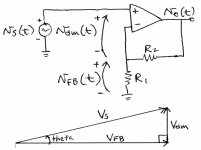
Let's see how this happens using phasors. Looking at the attachment below, the source voltage vS(t) must be equal to the sum of the feedback voltage vFB(t) and the difference-mode input voltage vdm(t). Let's ignore any possible distortion in these signals, and instead focus on how their components at the fundamental frequency must add up, so we can see how Gilbert's results come about. Since the fundamental components of these signals are sine waves with different amplitudes and phase angles, we must use phasor arithmetic to add them up. The upper case "V's" in the phasor diagram represent the amplitudes of their corresponding sinusoids. We assume a sinusoidal output voltage as Gilbert did. Let's assume its phase angle is zero. If the feedback network isn't loaded by the input diff amp, VFB will be just a scaled version of the output. Therefore its phase angle is also zero, so its phasor will be horizontal. By Gilbert's original assumption above, the output voltage (and also VFB) lags Vdm by 90 degrees. Equivalently, Vdm leads the output voltage (and VFB) by 90 degrees. Therefore, Vdm is pointing up, not down, and is at a right angle to VFB. When we do the phasor sum of VFB and Vdm, we get both the amplitude and phase of the input voltage VS. That's the hypoteneuse in the phasor diagram. To find out how much the output lags the input, we rotate the whole shebang so that VS is horizontal. We then see that the output lags the input by the angle theta (since the output is in phase with VFB).
Now the fun begins. Gilbert's assumption was of a BJT diff amp with no emitter degeneration. See figure 7 on this page by Marshall Leach for RE = 0. You can see that it doesn't take much difference-mode input voltage before it becomes nonlinear. If one applies a sine wave of large enough amplitude as the input voltage, the collector current will be a heavily clipped sine wave. Therefore this stage has lots of gain compression at even moderate difference-mode input voltages. Now there's one more thing we can observe about the phasor diagram. If we call the output amplitude Vo, we can see that VFB = R1 / (R1 + R2) * Vo. Therefore, in the phasor diagram, the length ratio VFB / Vdm is proportional to the magnitude of the open-loop gain. In fact, the magnitude of the open-loop gain is (1 + R2 / R1) * VFB / Vdm. Now, let's say we are at a fixed frequency and are varying the output amplitude. If magnitude of the open-loop gain were constant through all this, the ratio VFB / Vdm would also be constant (because it's proportional to the magnitude of the open-loop gain). By inspection of the phasor diagram, the angle theta, which is the input-output phase shift, would also be constant. So let's say we're at a pretty high and fixed frequency and we vary the output amplitude from being very tiny to very large. Because of the diff amp nonlinearity, we get compression in the open-loop gain at the high signal level. What this means is that because the open-loop gain is compressed, the ratio VFB / Vdm is changing with output amplitude. In fact, Vdm must be bigger than what it would be if the circuit were linear, to compensate for the gain compression. Since the large-signal Vdm / VFB is bigger than its small-signal value, we can see by inspection of the phasor diagram that theta, the input-output phase shift, must increase relative to its small-signal value. So there's our PIM. In short, because Vdm is in phase quadrature with VFB, gain compression in the open-loop amplifier gets converted to PIM in the closed-loop amplifier.
But PIM can happen in circuits without feedback too. If you're the type that messes with simulation using LTspice or similar, you might try simulating an output stage combined with drivers and possibly pre-drivers. Using a .FOUR command, you should be able to observe the phase angle of the fundamental frequency of the output changing a bit with input signal amplitude by inspecting the table in the SPICE error log. This is just another form of distortion, and the feedback doesn't know or care that it's PIM. It just reduces it like other distortions. So on the one hand, an amplifier having no open-loop PIM can end up with closed-loop PIM generated by the feedback. But an amplifier having some open-loop PIM, such as in the output stage, will have that PIM reduced by the feedback. In the case of Bob's PIM article, one ends up ahead in the PIM department by applying feedback, presumably because the reduction of open-loop PIM more than makes up for the PIM generated by the mechanism we've been discussing.
Attachments
stinius said:
and they sounded good, and they still do, but as far as I remember it was something wrong in the original Otala design about the NFB.
It reminds me:
"Sir colonel, do crocodiles fly?"
"Are you stupid? Never!"
"But Sir General said they do fly".
"Yes, but they fly on very-very low level!"
😀 😀 😀
While you were so busy in personal discussions we explained in many ways in this thread how PIMs happen (last pages), and all significant details of Otala amp (many pages ago). Can you please describe what was wrong in the original Otala design about NFB, except probably it's ratio on DC?
Anybody design any amplifiers here, lately, that are in the audio marketplace? I have a few, and am involved in a new design, that is quite radical. We shall see.
I still use negative feedback in large quantities in ALL my amplifiers. Only my best preamps and phono stages are free of global negative feedback, and it is not a pleasant experience to keep the distortion low.
Are any of my amps as good as a Halcro? Certainly not in absolutely low measurements. Halcro is the best, in my experience, in that regard. What I do, is offer twice the power, 9 times the peak current and lower high frequency output impedance than the Halcro, and less than 1/2 the price. Think of me as a Chevy, and Halcro as a Lincoln, if you will.
andy_c said:
Okay, I'm gonna give this a try. To keep the math to a minimum, I'll use a graphical approach as you suggested. I'll call this "The phasor perspective of feedback-generated PIM".
This analysis comes from Barrie Gilbert's article, Are Op Amps Really Linear?. In this article, Barrie makes some simplifying assumptions to keep the math from getting out of control. Here's the assumptions:
1) The only distortion of the circuit comes from the input stage. This is assumed to be a BJT stage with no emitter degeneration. Further, things like Early effect and nonlinear collector-base and base-emitter capacitance of the BJTs are neglected. The only nonlinearity that's taken into account is the exponential relationship between Vbe and collector current. This assumption leads to a mathematical expression between the diff amp's differential input voltage and its output current that takes the form of a hyperbolic tangent (or tanh()) function. The derivation of this function is in all the standard integrated circuits texts, but I'll only talk about it in general terms.
2) The diff amp's output current is converted to the op-amp's output voltage by an ideal integrator. This part of the circuit has no distortion, and because it's an integrator, the open-loop gain of the op-amp has a constant phase shift of -90 degrees from DC to daylight, and a magnitude that falls at 20 dB/decade (6 db/oct) from DC to daylight.
What he does might seem backwards at first, but is actually very useful and clever. He assumes the output voltage is an undistorted sine wave, then works his way back to the input voltage to see what it has to be to get the desired output voltage. He then shows that, at a fixed frequency, the input-output phase shift varies a bit with the amplitude of the signal. This is PIM, also called differential phase by video people. Sometimes it's also called AM-to-PM conversion, where PM stands for "phase modulation".
Let's see how this happens using phasors. Looking at the attachment below, the source voltage vS(t) must be equal to the sum of the feedback voltage vFB(t) and the difference-mode input voltage vdm(t). Let's ignore any possible distortion in these signals, and instead focus on how their components at the fundamental frequency must add up, so we can see how Gilbert's results come about. Since the fundamental components of these signals are sine waves with different amplitudes and phase angles, we must use phasor arithmetic to add them up. The upper case "V's" in the phasor diagram represent the amplitudes of their corresponding sinusoids. We assume a sinusoidal output voltage as Gilbert did. Let's assume its phase angle is zero. If the feedback network isn't loaded by the input diff amp, VFB will be just a scaled version of the output. Therefore its phase angle is also zero, so its phasor will be horizontal. By Gilbert's original assumption above, the output voltage (and also VFB) lags Vdm by 90 degrees. Equivalently, Vdm leads the output voltage (and VFB) by 90 degrees. Therefore, Vdm is pointing up, not down, and is at a right angle to VFB. When we do the phasor sum of VFB and Vdm, we get both the amplitude and phase of the input voltage VS. That's the hypoteneuse in the phasor diagram. To find out how much the output lags the input, we rotate the whole shebang so that VS is horizontal. We then see that the output lags the input by the angle theta (since the output is in phase with VFB).
Now the fun begins. Gilbert's assumption was of a BJT diff amp with no emitter degeneration. See figure 7 on this page by Marshall Leach for RE = 0. You can see that it doesn't take much difference-mode input voltage before it becomes nonlinear. If one applies a sine wave of large enough amplitude as the input voltage, the collector current will be a heavily clipped sine wave. Therefore this stage has lots of gain compression at even moderate difference-mode input voltages. Now there's one more thing we can observe about the phasor diagram. If we call the output amplitude Vo, we can see that VFB = R1 / (R1 + R2) * Vo. Therefore, in the phasor diagram, the length ratio VFB / Vdm is proportional to the magnitude of the open-loop gain. In fact, the magnitude of the open-loop gain is (1 + R2 / R1) * VFB / Vdm. Now, let's say we are at a fixed frequency and are varying the output amplitude. If magnitude of the open-loop gain were constant through all this, the ratio VFB / Vdm would also be constant (because it's proportional to the magnitude of the open-loop gain). By inspection of the phasor diagram, the angle theta, which is the input-output phase shift, would also be constant. So let's say we're at a pretty high and fixed frequency and we vary the output amplitude from being very tiny to very large. Because of the diff amp nonlinearity, we get compression in the open-loop gain at the high signal level. What this means is that because the open-loop gain is compressed, the ratio VFB / Vdm is changing with output amplitude. In fact, Vdm must be bigger than what it would be if the circuit were linear, to compensate for the gain compression. Since the large-signal Vdm / VFB is bigger than its small-signal value, we can see by inspection of the phasor diagram that theta, the input-output phase shift, must increase relative to its small-signal value. So there's our PIM. In short, because Vdm is in phase quadrature with VFB, gain compression in the open-loop amplifier gets converted to PIM in the closed-loop amplifier.
But PIM can happen in circuits without feedback too. If you're the type that messes with simulation using LTspice or similar, you might try simulating an output stage combined with drivers and possibly pre-drivers. Using a .FOUR command, you should be able to observe the phase angle of the fundamental frequency of the output changing a bit with input signal amplitude by inspecting the table in the SPICE error log. This is just another form of distortion, and the feedback doesn't know or care that it's PIM. It just reduces it like other distortions. So on the one hand, an amplifier having no open-loop PIM can end up with closed-loop PIM generated by the feedback. But an amplifier having some open-loop PIM, such as in the output stage, will have that PIM reduced by the feedback. In the case of Bob's PIM article, one ends up ahead in the PIM department by applying feedback, presumably because the reduction of open-loop PIM more than makes up for the PIM generated by the mechanism we've been discussing.
Hi Andy,
You are EXACTLY on target!
BTW, I have used the input-referred feedback/distortion analysis often, and it is very useful.
I believe your description is right in line with Barrie Gilbert's as well.
You are also right on target in regard to pre-existing PIM versus PIM generated by NFB.
Here is one thing to note, however. We need to go further, and even more fun lies ahead. Barrie Gilbert's analysis (and yours) assumes a perfect integrator for the VAS. This reflects the case of very high feedback factor and very low open-loop bandwidth.
The point of disagreement between me and Matti is not whether PIM exists or is generated by negative feedback (it does and it is), but rather how the application of different types of negative feedback affect the generation of PIM by NFB.
Otala asserted that high NFB and low open-loop bandwidth made PIM worse. Perhaps more accurately, he asserted that less feedback and higher open-loop bandwidth would reduce feedback-generated PIM.
My analysis indicates that the amount of PIM generated by NFB will be largely independent of the amount of negative feedback and open-loop bandwidth as long as the closed loop bandwidth is the same. The reason for this is simple. The usual analysis, including Barrie's, results in an amplifier whose closed loop frequency response has a single pole at the gain crossover frequency of the NFB. We all know that the variation in input stage gm (the compression you referred to) will cause the gain crossover frequency to move back and forth. The phase of this closed loop pole at audio frequencies is the same as the phase you arrived at with the phasor diagram. Therefore, the PIM can also be viewed as resulting from the movement of the NFB gain crossover frequency and the closed-loop pole.
So here is the important point. The gain crossover frequency is not strongly influenced by the open-loop bandwidth and amount of low-frequency NFB. It is set by the gain-bandwidth product established by the compensation.
Two amplifiers, each with a closed-loop bandwidth of 500 kHz, will have essentially the same behavior of the closed loop pole frequency even if one amplifier has low open loop bandwidth and the other has high open-loop bandwidth.
Finally, it is fair to say that there likely exists a gray region for values of negative feedback substantially less than 20 dB where these simplified views lose some of their accuracy. This is not to say that PIM gets better or worse if you build an amplifier with only 10 dB of negative feedback.
Cheers,
Bob

john curl said:Anybody design any amplifiers here, lately, that are in the audio marketplace? I have a few, and am involved in a new design, that is quite radical. We shall see.
I still use negative feedback in large quantities in ALL my amplifiers. Only my best preamps and phono stages are free of global negative feedback, and it is not a pleasant experience to keep the distortion low.
Are any of my amps as good as a Halcro? Certainly not in absolutely low measurements. Halcro is the best, in my experience, in that regard. What I do, is offer twice the power, 9 times the peak current and lower high frequency output impedance than the Halcro, and less than 1/2 the price. Think of me as a Chevy, and Halcro as a Lincoln, if you will.
John, you make a great amp, regarless of the money. I think of you more as a Lexus than a Chevy.
Cheers,
Bob
Bob, Andy,
I guess that when approaching slew rate limiting, you would also see modulation of the GBW product. That would mean that at the onset of slew rate limiting, higher levels of PIM would be generated. Agree?
Edit: spelling
Jan Didden
I guess that when approaching slew rate limiting, you would also see modulation of the GBW product. That would mean that at the onset of slew rate limiting, higher levels of PIM would be generated. Agree?
Edit: spelling
Jan Didden
Any non-linearity will cause PIM in presence of in-band phase shift and feedback. Even Kirk and Early effects in output devices.
Bob Cordell said:Here is one thing to note, however. We need to go further, and even more fun lies ahead. Barrie Gilbert's analysis (and yours) assumes a perfect integrator for the VAS. This reflects the case of very high feedback factor and very low open-loop bandwidth.
Hi Bob,
I agree with you here. A while back, I extended Gilbert's analysis to cover the case where the open-loop gain was not an integrator and the nonlinear transfer characteristic of the input stage was not the same as what you get when using undegenerated BJTs. That is shown here. The math got pretty messy. Once I found out by playing around with SPICE that if you use the typical 100 Ohm emitter degeneration resistors for the input stage, that common-mode effects were an order of magnitude higher, I kind of lost interest. It ends up being a whole bunch of math for something that's not even the dominant input stage distortion to begin with.
Still, regardless of one's opinion of Otala, everyone seems to agree on the "He made us think" thing, and that reflects on the technical part of the discussion here. So it's a worthwhile thought experiment even if it's not the dominant distortion mechanism of the input stage of a power amp.
Can anyone point out to me what the 'open loop bandwidh' is of an AD825 or an AD829? Please, I need to know.
janneman said:Bob, Andy,
I guess that when approaching slew rate limiting, you would also see modulation of the GBW product. That would mean that at the onset of slew rate limiting, higher levels of PIM would be generated. Agree?
Edit: spelling
Jan Didden
Yes, I think that would be the case.
Cheers,
Bob
- Home
- Amplifiers
- Solid State
- Matti Otala - An Amplifier Milestone. Dead or Alive