Last night I went to an Oklahoma City symphony concert with Sarah Coburn singing opera favorites to "calibrate my ears" for tweaking my sound. Above I said my output filter was slightly dull sounding, but that was yesterday's results. After listening to the setup today, I found the calculated filter to best match the sound of the symphony last night. Hooray for matching the output filter to my speakers!
I also tried swapping out improved 10uF inductors for the Sure 10uF inductors I was using and thought the sound was slightly cleaner for the improved ones. Maybe I am fooling myself, but Trevor did say that there are distortion differences between output inductors in his analysis on his web site. For my test of his output filter, I ordered the ICE inductors he recommended. I am looking forward to that this next week.
I also tried swapping out improved 10uF inductors for the Sure 10uF inductors I was using and thought the sound was slightly cleaner for the improved ones. Maybe I am fooling myself, but Trevor did say that there are distortion differences between output inductors in his analysis on his web site. For my test of his output filter, I ordered the ICE inductors he recommended. I am looking forward to that this next week.
I just thought that if you are using a second order, or greater, low pass filter on a mid driver in a multi-amp situation, you might be able to eliminate the entire amp output filter and move the speaker's filter, physically, to immediately after the amp. The speaker's filter should have a low enough cutoff freq to effectively remove the switching freq. This eliminates the amp's output filter as a distortion causing device. It could be that it will not make a difference because the mid's cutoff freq is so low that any distortion introduced by the amps output filter will be negligible. I am just thinking as a speaker designer would, and seeing the amp's output filter as just another speaker (crossover like) filter.Perhaps the misunderstanding is that it is perhaps possible to eliminate the zobel, which is part of the overall output filter... ?
I just thought that if you are using a second order, or greater, low pass filter on a mid driver in a multi-amp situation, you might be able to eliminate the entire amp output filter and move the speaker's filter, physically, to immediately after the amp. The speaker's filter should have a low enough cutoff freq to effectively remove the switching freq. This eliminates the amp's output filter as a distortion causing device. It could be that it will not make a difference because the mid's cutoff freq is so low that any distortion introduced by the amps output filter will be negligible. I am just thinking as a speaker designer would, and seeing the amp's output filter as just another speaker (crossover like) filter.
Yes, an interesting idea indeed. It's a multi-faceted subject 🙂
On the way to exerise, I realized that the whole idea of ever removing the output filter and zobel is a bad idea (unless you really know what you are doing, like those papers that talk about a filterless class-d amp).
I realized that an air core inductor in a speaker crossover would broadcast RF like crazy without the output filter, and even one with an iron core would still broadcast more than is good.
As for the zobel, you need it for when your speakers are disconnected from the amp. So, anyone reading this thread, forget about removing the output filter.
Just design your own output filter to match your speakers. The process is easier than trying to design your own conventional output filter (which would probably take filter design software to get right).
James
But can you only use the tweeter data when you calculates the filter? For instance, my speakers tweeter has 4,7 nominell input impedance (and 0.05mh inductance). But when I look on a impedance graph for the whole speaker, the speakers impedance doesn't dip below 7 ohm (20hz-30khz). That would suggest (i think) some serie resistans with the tweeter in the speakers filter, should I add that to the speakers impedance (maybe some 3 ohms or so) when I do the calculations?
Yes, you are right that you have to take the crossover into account. If you can, disconnect the tweeter circuit from the rest of the speaker and measure with the tweeter crossover in place. Probably should have said that up front.
James
James
That's the best idea for all newbies. That's where I started. It answers most questions newbies have in the beginning and gives information on the conventional approach to output filters. I was surprised that there was nothing on matching the output filter exactly to your own speakers. Being a speaker person, I thought that was a very straight forward approach, and easier than using Spice to design a conventional output filter as Trevor did. Any DIY speaker person would appreciate the approach. It isn't as easy, however, as just using a well designed output filter like Trevor's. Still speaker people will appreciate the elegance of a calculated match.
James 🙂
James 🙂
Mouser delivered the parts for my latest test this morning. I compared Trevor Marshall's Spice designed conventional output filter to my output filter that was matched to my speakers. Trevor's measurements show that into a purely resistive 4 and 8 ohm load, the response peaks VERY slightly into 8 ohms and rolls off very slightly into 4 ohms, and is worlds better than the Sure designed output filter that was designed for the board he tested.
Well, I cannot tell the difference between the two without setting up a rapid AB switch. To me this is good news. It means that my filter worked as well as a very well designed output filter, and while I am not able to do the same analysis that Trevor used, I was able to design an equally good filter using the technique I've promoted in this thread.
James 🙂
That's the best idea for all newbies. That's where I started. It answers most questions newbies have in the beginning and gives information on the conventional approach to output filters. I was surprised that there was nothing on matching the output filter exactly to your own speakers. Being a speaker person, I thought that was a very straight forward approach, and easier than using Spice to design a conventional output filter as Trevor did. Any DIY speaker person would appreciate the approach. It isn't as easy, however, as just using a well designed output filter like Trevor's. Still speaker people will appreciate the elegance of a calculated match.
James 🙂
Oh sorry 🙁 I just mentioned the wiki because I thought you had 33uH inductors there . Nevermind
Great work
[]'s
Last edited:
Hi
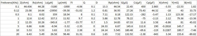
I have just measured my Loudspeaker (Royd Sintra II) with an LCR meter.
I got these values @1V
(KHz)___Z(ohm)____Rs(ohm)__Ls(µH)___Lp(mH)
0.1____44.436_____44.28____-5180____-1000
0.12___23.08______14.64____-23950___-39.58
0.5_____8.1________8.02_____359_____18.54
1_____12.6________12.42____337.3____11.92
2_____12.35_______10.26____-545.8____-1.77
5______6.86________6.86____-8.94_____-5.32
10 5.53 5.53 3.63 2.13
20 6.43 5.49 26.58 98.46
I'm a little bit confused about the value to chose for Rs .
I think I will use a 15µH inductor.
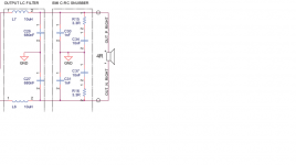
When I read about Zobel filter I can't find a digram that match the one for my amp(se attachment).
Please give some help🙂
Thanks in advance
Bjarne
I have just measured my Loudspeaker (Royd Sintra II) with an LCR meter.
I got these values @1V
(KHz)___Z(ohm)____Rs(ohm)__Ls(µH)___Lp(mH)
0.1____44.436_____44.28____-5180____-1000
0.12___23.08______14.64____-23950___-39.58
0.5_____8.1________8.02_____359_____18.54
1_____12.6________12.42____337.3____11.92
2_____12.35_______10.26____-545.8____-1.77
5______6.86________6.86____-8.94_____-5.32
10 5.53 5.53 3.63 2.13
20 6.43 5.49 26.58 98.46
I'm a little bit confused about the value to chose for Rs .
I think I will use a 15µH inductor.
When I read about Zobel filter I can't find a digram that match the one for my amp(se attachment).
Please give some help🙂
Thanks in advance
Bjarne
Attachments
Last edited:
IRS2092 designs from IR don't use a zobel network.
Yes they do Nigel ,
Cheers ,
Rens
Yes they do Nigel ,
Cheers ,
Rens
There isn't one in the application notes.
There isn't one in the application notes.
Page 29 Iraudamp 7s:
"The IRAUDAMP7S has an RC network called Zobel network (R30 and C13) to damp the
resonance and prevent peaking frequency response with light loading impedance. (Fig 32) The
Zobel network is not thermally rated to handle continuous supersonic frequencies above 20kHz.
These supersonic input frequencies can be filtered out by adding R2 and C2 as shown on main
schematic Fig 33 and Fig 34. This RC filter works also as an input RF filter to prevent potential
radio frequency interferences."
Cheers ,
Rens
no Zobel at all
I have a Sure board 4 x 100w which was supplied with the R and C missing i.e. no Zobel network at all. I have not yet used the board so cannot comment on performance, anyone else have such a board?
I have a Sure board 4 x 100w which was supplied with the R and C missing i.e. no Zobel network at all. I have not yet used the board so cannot comment on performance, anyone else have such a board?
IRS2092 designs from IR don't use a zobel network.
But my board has a TPA3116 chip.
I found specification on my tweeter:
Rs=5,7ohm
Ls=0,08mH
I will use a inductor = 0, 15mH
If I use the formula: fbtl=1000*(0.2251*0.5*5,7)/0,0075
fbtl = 85538Hz
Cbtl=1000000*(0.1125/(0.5*5,7*85538))
Cbtl=461nF
But what about the Snupper(se diagram). Shall I use other values here or how do I calculate new values.
Or shall I bypass the snubber and calculate a new Zobel filter and use an adon board ?
Regards Bjarne
Attachments
Last edited:
But what about the Snupper(se diagram). Shall I use other values here or how do I calculate new values.
Or shall I bypass the snubber and calculate a new Zobel filter and use an adon board ?
Regards Bjarne
4r7 3w and 100nf.
- Status
- Not open for further replies.
- Home
- Amplifiers
- Class D
- Match Your Output Filter to Your Speakers - All Boards Welcome