I made an inductive Phono Stage for Fast Audio called "Tanzmusik".
One advantage of that stage is that the coil is in a feedback loop to ground in the MM stage.
That coil has less then 10 Ohm DC impedance where normally is a ca. 200 Ohm resistor so it has less noise. It terms of sound it sounded " fatter" and more robust.
I would say a matter of taste. My job was to create a kind of vintage sound anyway.
Rock and Jazz-Rock from the 70th sounds very familiar on this one where modern stages can sound a little threadbare so it compensates a bit for flaws in the recording.
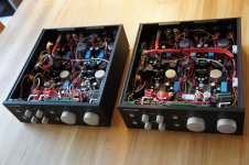
It is pretty complex.
It has two MC inputs, one active, one transformer coupled.
It has an MM input and direct output.
It has a tube line stage with volume control that also has a headphone output.
It has treble and bass control for both channels separate and a RIAA look that switches out the tone control.
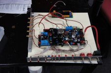
There is an external PSU with a lot of transformers and regulation for the tube and active stages, double mono.
It has two MC inputs, one active, one transformer coupled.
It has an MM input and direct output.
It has a tube line stage with volume control that also has a headphone output.
It has treble and bass control for both channels separate and a RIAA look that switches out the tone control.
There is an external PSU with a lot of transformers and regulation for the tube and active stages, double mono.
Here is a thread about LCR RIAA´s.
They need resistors and caps too.
I do NOT use this topology.
http://www.diyaudio.com/forums/tubes-valves/227736-riaa-lcr-mythos.html#post3482493
They need resistors and caps too.
I do NOT use this topology.
http://www.diyaudio.com/forums/tubes-valves/227736-riaa-lcr-mythos.html#post3482493
question:
what bench tests would you recommend to test the shunt supply overall in terms of ripple rejection and stability of design?
what bench tests would you recommend to test the shunt supply overall in terms of ripple rejection and stability of design?
Partly it can be simulated, for example output impedance over frequency.
A high speed scope also helps tremendous to track down oscillation.
A high speed scope also helps tremendous to track down oscillation.
I mean test to evaluate voltage rejection, output impedance, frequency response.
I am assuming that rejection can be fairly easy as some noise can be cap coupled to the input of the supply and measure the attenuation at the output.
Maybe output impedance could be harder.
I have a 400MHz scope, I think it should suffice to check out oscillation.
One time I had access to the best tektronix 1-2GHz Scope and Top aginent specutrim analyzer. 😱
yeah it looks like you need a spectrum analyzer with isolation tranformer to perform all these tests.
well, that is wrong
it is frequency into time and vice versa
Fast Fourier transform - Wikipedia, the free encyclopedia
it is frequency into time and vice versa
Fast Fourier transform - Wikipedia, the free encyclopedia
well, that is wrong
it is frequency into time and vice versa
Fast Fourier transform - Wikipedia, the free encyclopedia
yes this is correct.
I am wondering if there is a simpler way to test things without involving a dedicated spectrum analyzer!
You could simulate the input impedance of your phono stage on the power line.
You can then ballast ( in simulation ) the PSU with that impedance.
Or can you can simply build the real thing and probe the connection between the PSU and the phono stage. Unfortunately that gives you only the status quo and will not tell you what went wrong.
You can then ballast ( in simulation ) the PSU with that impedance.
Or can you can simply build the real thing and probe the connection between the PSU and the phono stage. Unfortunately that gives you only the status quo and will not tell you what went wrong.
Last edited:
question:
what bench tests would you recommend to test the shunt supply overall in terms of ripple rejection and stability of design?
Something like this
Attachments

- Status
- Not open for further replies.
- Home
- Source & Line
- Analogue Source
- Masterpiece