Hi,
I have a Rotel RB-991 which is not only a poor match for my speakers, but gets heavily slated on this site.
This was the original problem, now considering a more drastic solution.
http://www.diyaudio.com/forums/solid-state/170486-rotel-rb991-vs-acoustic-energy-309-fail.html
For a summary, speakers are very sensitive, amp only sounds good when being driven more than 20%, which is way to loud for my room.
Now I do not want to stick the RB-991 in the bin and start again, and I cannot sell due to some basic mods which have ruined the look of the case (speakon connectors being the main one.)
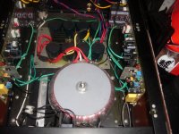
I am thinking that the transformer/power supply/main caps are worth keeping.
Is their a good DIY board that I could slot in where the current ones go, taking advantage of the good heatsinks, supply, caps?
Any suggestions?
I believe the rail voltages on this are 70v, might be wrong, not even sure if it is relevant.
Are these coke can sized caps just used to maintain the supply or are they used for something else?
A quick example of how sensitive these speakers are, would be what I am currently driving them with. A modded SonicT can happily drive these speakers to a level that is uncomfortable. I should add this room is large, 5mx15m.
I have no ideas where to start or what to do, so this is an early stage research.
Any suggestions/ideas?
No budget at the moment (as no job), so quite open on that (no more than a few hundred though, hopefully a lot less)
I have a Rotel RB-991 which is not only a poor match for my speakers, but gets heavily slated on this site.
This was the original problem, now considering a more drastic solution.
http://www.diyaudio.com/forums/solid-state/170486-rotel-rb991-vs-acoustic-energy-309-fail.html
For a summary, speakers are very sensitive, amp only sounds good when being driven more than 20%, which is way to loud for my room.
Now I do not want to stick the RB-991 in the bin and start again, and I cannot sell due to some basic mods which have ruined the look of the case (speakon connectors being the main one.)
I am thinking that the transformer/power supply/main caps are worth keeping.
Is their a good DIY board that I could slot in where the current ones go, taking advantage of the good heatsinks, supply, caps?
Any suggestions?
I believe the rail voltages on this are 70v, might be wrong, not even sure if it is relevant.
Are these coke can sized caps just used to maintain the supply or are they used for something else?
A quick example of how sensitive these speakers are, would be what I am currently driving them with. A modded SonicT can happily drive these speakers to a level that is uncomfortable. I should add this room is large, 5mx15m.
I have no ideas where to start or what to do, so this is an early stage research.
Any suggestions/ideas?
No budget at the moment (as no job), so quite open on that (no more than a few hundred though, hopefully a lot less)
I doubt there is any drop in board.
The large cans are indeed the main power supply capacitors. The rail voltages are about 75v unloaded (depending on mains voltage).
Now I remember that I commented on your other thread - did you try increasing the bias, and did that help?
The large cans are indeed the main power supply capacitors. The rail voltages are about 75v unloaded (depending on mains voltage).
Now I remember that I commented on your other thread - did you try increasing the bias, and did that help?
Hi Jayce,
I increased the bias, but didn't notice any difference =-(
Can't remember what I set it to, will check again when the spare parts arrive (one of the power smoothing caps leaked).
My knowledge of amps is small, but this is how I see the situation.
I have a good quality 75v power supply and balanced inputs. All I think I need is an amplification board that runs off 75v and I should just be able to swap the cables over and get a new amp.
Is my view logical, or so over simplified that it won't work?
If one of the smoothing caps has leaked, this is a sign of trouble in itself. Yes, sorry to say it is a very simplistic view. It's like saying you can take a Ford Escort, put a Ferarri engine in it and get an Enzo. I hope im not sounding too harsh there 🙂
Thing is, the Rotel shouldn't sound that bad at all. Now you mention a smoothing capacitor has leaked, it tells me theres a problem with it.
Thing is, the Rotel shouldn't sound that bad at all. Now you mention a smoothing capacitor has leaked, it tells me theres a problem with it.
Can we see a schematic of this amp ?..
Rotel had quite a few good amps, unfortunately there are
some design choices that can make a basicaly good amp
sounding mediocre.
Particularly, they rely on massive shunt compensations that
litteraly kill the amp s qualities if implemented as heavily..
Rotel had quite a few good amps, unfortunately there are
some design choices that can make a basicaly good amp
sounding mediocre.
Particularly, they rely on massive shunt compensations that
litteraly kill the amp s qualities if implemented as heavily..
Can we see a schematic of this amp ?..
The cap that leaked was C803.
Not certain what that board does, but as the protection and power LEDs are linked to it my guess is the protection circuit, Rotel tech said it was a power smoothing cap.
Not certain what that board does, but as the protection and power LEDs are linked to it my guess is the protection circuit, Rotel tech said it was a power smoothing cap.
It is indeed the protection board - Strange for the cap to leak, but it wouldn't cause poor sound issues.
The RB991 would certainly make a great chassis for a different amp, but it would be strictly DIY, nothing drop-in.
The RB991 would certainly make a great chassis for a different amp, but it would be strictly DIY, nothing drop-in.
Can we see a schematic of this amp ?..Yes ;-) Service Manuals
Thank you, Aparatusonus
I once had a gif schematic and it s exactly this one , safe
that your link gives the full version.
A very fine amp and i once made some sims to see its behaviour.
Seems to me that compensation is heavy and doesn t help the
dynamic behaviour.
Also, the input differentials have no degeneration.
All in all , it should be slightly modded to give its best ,
since the topology is quite good.
Can we see a schematic of this amp ?..
Thank you, Aparatusonus
I once had a gif schematic and it s exactly this one , safe
that your link gives the full version.
A very fine amp and i once made some sims to see its behaviour.
Seems to me that compensation is heavy and doesn t help the
dynamic behaviour.
Also, the input differentials have no degeneration.
All in all , it should be slightly modded to give its best ,
since the topology is quite good.
This sounds promising!
I was worried when I got this amp that it seemed a little too good on paper. I thought there might have been a compromise to get the distortion that low and damping that high.
If one of the smoothing caps has leaked, this is a sign of trouble in itself. Yes, sorry to say it is a very simplistic view. It's like saying you can take a Ford Escort, put a Ferarri engine in it and get an Enzo. I hope im not sounding too harsh there 🙂
.
Not harsh at all, I am an electrician, not an 'electronician', so know there are HUGE gaps in my knowledge from the simplified training?
I was thinking something along these lines.
DIY Audio Power Amplifier modules : DIY Audio
It is a drop in amp module with a separate power supply module.
I thought if I could find a module like this that runs on 75v it could work.
I would appreciate it, if you could expand a little on why that would not work.
Thanks,
P
Hmm, to be honest I didn't consider that option at all. That could indeed work. 75V means quite a high output wattage, thats getting a little bit out of the realms of kits but its doable.
To be quite honest, with speakers so sensitive, you probably only need 50-100W of amplifier. If budget is a concern, it's probably going to work out more cost effective to sell your Rotel and buy/build another. I know you have modified your amp with Speakon sockets etc but you would probably still find a buyer on eBay or so.
To be quite honest, with speakers so sensitive, you probably only need 50-100W of amplifier. If budget is a concern, it's probably going to work out more cost effective to sell your Rotel and buy/build another. I know you have modified your amp with Speakon sockets etc but you would probably still find a buyer on eBay or so.
If all else fails you could try using a CDA-258 from Class D Audio which will run off 75 volt dc rails.If you dont like it you can return it within 7 days of receiving the module. I personally own an SDS-254 and it sounds fantastic at all levels on my Maggnepan MMG's.
Thanks for the suggestions Stigs, but not really looking for a class D design.
I am about to give my class AB 200w BJT creation a facelift (build a new PCB). It runs on 75 volt rails. I had the same circumstances as you , a old Genesis stealth case with monster 1KVA trafo / 80K uf power supply, extremely large heatsinks ,too.
I gutted it , bolted the trafo with the proper hardware and began to build. (Below 1 -2) fit easily into the classic case. I am now in the process of upgrading to the sprint layout pro board I just made and feel they would be wonderful suggestion for a large rotel (pictures ???) It is a shame , I might be throwing the boards pictured below in the amp out... to be replaced (by pix3-4).
OS
Attachments

Last edited:
Wahab's right about them using shunt compensation and no emitter degeneration. Not great design choices. But the fact that it sounds OK above a certain volume level screams 'grounding' at me. This can be fixed at very low cost but substantial time investment.
Wahab's right about them using shunt compensation and no emitter degeneration. Not great design choices. But the fact that it sounds OK above a certain volume level screams 'grounding' at me. This can be fixed at very low cost but substantial time investment.
Thanks to going back to college I have a lot of free time, but little money.
There is a ground loop issue (I have got another thread on this), but this problem is extant when the PC is not connected (hence no ground loop).
I started a separate thread on this as believed a separate problem, but you mention grounding, so.
http://www.diyaudio.com/forums/anal...-above-me-xlr-vs-ground-loop.html#post2382800
would it be possible to correct the shunt compensation and emitter degeneration, or is there a chance they are there to compensate for something else?
I read up on shunt and emitters, but although most of the words made sense, the application was above me.
Thanks for your help so far everyone.
Fact is that this amp should sound nice as it is.
True that compensation is heavy; but since they use
a triple emitter follower configuration, it s somewhat
needed to keep the thing stable.
The amp s input low pass filter seems also quite loud
in his influence, consisting of 1K + 470R and a 680pF cap.
This latter should be reduced to 220pF to retain a correct
slew rate..
Thanks to going back to college I have a lot of free time, but little money.
That's cool, re-grounding as an approach to improving your sound quality should appeal to you 😀
There is a ground loop issue (I have got another thread on this)
Yes, you mention you're running balanced between the RC-995 and the RB-991. So the first port of call when trying to find out what's knackering your sound is those balanced inputs...
And indeed they break the cardinal rule for running balanced, which is to wire the pin1 directly to chassis. Instead they put a cap to chassis but take the DC path onto the input board where sits an opamp susceptible to RF. Re-rigging the grounds here is a matter of doing it by the book - hardwire pin1 to chassis (i.e. short out the caps C513 & C514) and break the pin1 - PCB connections. This I reckon might give you a sound quality improvement all by itself. Its fortunate you don't have to fiddle with the decoupling ground, that already has its own return on the input boards.
...would it be possible to correct the shunt compensation and emitter degeneration, or is there a chance they are there to compensate for something else?
Certainly its possible, but it does require some knowledge of the gain vs frequency response to get it right. A first off stab would be to put 47R in series with the emitters of the LTPs (Q601,Q603,Q607 & Q609), this will tend to improve stability but may also worsen distortion as it reduces the OLG. Halving the values of the shunt caps (C609, C613 & C615 on one channel - my god, there's 3 of them!) might compensate for that but really should be done with care and a scope to check for instability. Its generally regarded as better to create a feedback loop around the VAS transistors (that's Q613 & Q615) with those caps, but let's take this one step at a time.🙂
- Status
- Not open for further replies.
- Home
- Amplifiers
- Solid State
- Massive amp modification - basic questions - Rotel RB991 donor