selecting jfets
When selecting jfets, what happens if I select a pair that measure 0.7ma Ids, or a pair that measure 1.0ma Ids? Provided that the compliments can be matched to each other, which direction (if any) provides better (or worse) thd and/or absolute drift? Is there something in the data sheet that provides this info, or is it tribal knowledge?
When selecting jfets, what happens if I select a pair that measure 0.7ma Ids, or a pair that measure 1.0ma Ids? Provided that the compliments can be matched to each other, which direction (if any) provides better (or worse) thd and/or absolute drift? Is there something in the data sheet that provides this info, or is it tribal knowledge?
I want to say thank you for R.N Marsh. This thread was inspiring me to make a pre-amp with CFA topology using JFET as input (2SK246 and 2SJ103, although 2SK170 and 22SJ74 is better on simulation, they are hard to find and expensive).
I made a demonstration to my friends. We use my amplifiers, Sysmasym, and Gainclone LM3886. This pre-amp make all amplifier sound better and stereo image wider.
I made a demonstration to my friends. We use my amplifiers, Sysmasym, and Gainclone LM3886. This pre-amp make all amplifier sound better and stereo image wider.
With help from Preamp I was using ARTA to do some tests on a PSU I built.
ARTA has a good rep. You might also look at HpW Works for your distortion analysis. [Home ]
An interesting piece of software i also use is: SpectraPLUS - Home Page : Acoustics and Vibration : FFT Spectrum Analyzer : SpectraPlus.com
THx-RNMarsh
When selecting jfets, what happens if I select a pair that measure 0.7ma Ids, or a pair that measure 1.0ma Ids? Provided that the compliments can be matched to each other, which direction (if any) provides better (or worse) thd and/or absolute drift? Is there something in the data sheet that provides this info, or is it tribal knowledge?
Hi.... since this is direct-coupled stages, the current thru the IPS must stay as original or all eise gets upset and may not be optimum. Stay with 1mA. This is also the zero TempCo point for these fets.
THx-RNMarsh
Art of Design
Thank you. I did the design for myself, but when I heard it, I had to publish it so others would know its sound and performance. The CFA discussion which followed tried to figure out why CFA sounds so good. The HPA circuit here is a hybrid topology and one I found years ago to perform best.
The best results are found in the details.
In an attempt to measure its distortion, I made another journey into distortion measurements on another forum.
The many different directions this has taken me, has been a lot of fun. And, learning new details and finding other curious minds is always a pleasure. 🙂
In the end, for me, the art of design is for and about the enjoyment of the art of music.
THx-RNM
I want to say thank you for R.N Marsh. This thread was inspiring me to make a pre-amp with CFA topology using JFET as input (2SK246 and 2SJ103, although 2SK170 and 22SJ74 is better on simulation, they are hard to find and expensive).
I made a demonstration to my friends. We use my amplifiers, Sysmasym, and Gainclone LM3886. This pre-amp make all amplifier sound better and stereo image wider.
Thank you. I did the design for myself, but when I heard it, I had to publish it so others would know its sound and performance. The CFA discussion which followed tried to figure out why CFA sounds so good. The HPA circuit here is a hybrid topology and one I found years ago to perform best.
The best results are found in the details.
In an attempt to measure its distortion, I made another journey into distortion measurements on another forum.
The many different directions this has taken me, has been a lot of fun. And, learning new details and finding other curious minds is always a pleasure. 🙂
In the end, for me, the art of design is for and about the enjoyment of the art of music.
THx-RNM
Last edited:
The output stage (OPS) contributes to lowered over-all distortion. There is a 10dB reduction in THD or 3 times reduction with the added OP transistor compared to just a single pair of complimentary followers.
And a like-wise substantial reduction is seen when operated at higher PS voltages [24vdc].
THx-RNMarsh
And a like-wise substantial reduction is seen when operated at higher PS voltages [24vdc].
THx-RNMarsh
but what about heat dissipation at +-24V ?
It wont be a problem. They are each 15W, 5 Amp devices. With a pre- existing heat sink used with lower PS voltage, will still be OK IMO.
The devices nonlinear C drops to 1/3 and thus further reduce THD.... along with greater dynamic range and ability to drive to even lower Z loads. If thats desired.
It's just something some might want to try.
THx-RNMarsh
It wont be a problem.
THx-RNMarsh
Except that the heat dissipated by the output devices themselves is directly related to the square of the sum of rail voltages. With +/- 24V rails (vs +/- 12V) they burn 4x the amount of energy.
Thus, heat sink appropriately.
Except that the heat dissipated by the output devices themselves is directly related to the square of the sum of rail voltages. With +/- 24V rails (vs +/- 12V) they burn 4x the amount of energy.
Thus, heat sink appropriately.
It wont hurt to heat-sink more..... however, i measured the temp rise going from 15v to 24v without any heat sink at all on the power transistors. The device temp on its metal back went to 70C using 24vdc supplies.
THx-RNMarsh
I bought the topic from Linear Audio. But I didn't see any bias for each stage in the documents especially the ouput stage (CFP pairs - for first tran and second tran). Could you help me on this?
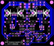
Nice looking pcb.
Are there any other builders who have comments on its audio/music performance?
Let me know what you think and what headphones were used etc.
THx-RNMarsh
Are there any other builders who have comments on its audio/music performance?
Let me know what you think and what headphones were used etc.
THx-RNMarsh
Hi,
almost a year I listen music through your amplifier with AT ATH M50x phones.
My amp configuration: 2sk170/2sj74 input, MPS 8599/8099 bjts and BD 139/140 outputs - biased somewhat higher then in article and +-15V psu with standard LM regs in big enclosure. very low DC offset and nice sounding amp - I like it very much. tnx for schematic.
Hi,
almost a year I listen music through your amplifier with AT ATH M50x phones.
My amp configuration: 2sk170/2sj74 input, MPS 8599/8099 bjts and BD 139/140 outputs - biased somewhat higher then in article and +-15V psu with standard LM regs in big enclosure. very low DC offset and nice sounding amp - I like it very much. tnx for schematic.
Hi, I plan to use 2sk170/2sj74 as input, too. Could I ask for your devices's Idss and bias of the first stage?
Ok i will measure bias.but idss if i remember correctly-about 9 or so.
Thanks! I asked because I plan to use 2SK170/2SJ74 near Idss. I think Richard choose 1mA for 2N5457/2N5460 because it is "zero temperature coefficient". With 2SK170/2SJ74 the "zero temperature coefficient" is about 12-13mA as "Erno Borbely" point out, we can't get there if we doesn't have V grade jfet. So I want to use 80% of the Idss as bias for first stage like some Pass amp/preamp.
just measured : front jfets sitting around 5mA (on the same pcb i have Pass B1 with 8mA bias) may be i should rise front bias a little ? offset setting is a bit tricky -i cover the amp and then wait few minutes to warm it up and then adjust offset with multi turn pot.
- Home
- Amplifiers
- Headphone Systems
- Marsh headphone amp from Linear Audio