Hi Andre,
I also did not find any suspicious solder joints when looking on the boards, nevertheless I resoldered EVERY joint; obviously in my case crackling noise had been due to bad solder joints which became old - I took out both PCB's and resoldered them and slightly turned the trimpots. After that action the crackling disappeared. Especially look at the semiconductors with heatsinks (Q119 - 122) because they are becoming pretty hot.
Good luck!
Dieter
Hi Dieter, thanks for the repply. I had really gone over all the Q119- 122 joints thoroughly but perhaps had not turned all the channel trimpots enough... The crackling noise did go away for a day or so but sadly it was back again today (although not as loud) . I'm wondering now if it could be caused by a bad cap or opamp? So far, from what I came across on the net, this cracking noise only seems to afflict the left channel of the no. 431. amps! I mean, unless ML used different components building the right channel, I cant figure out why this would be. This simply doesn't make any sense to me.Hi Andre,
I also did not find any suspicious solder joints when looking on the boards, nevertheless I resoldered EVERY joint; obviously in my case crackling noise had been due to bad solder joints which became old - I took out both PCB's and resoldered them and slightly turned the trimpots. After that action the crackling disappeared. Especially look at the semiconductors with heatsinks (Q119 - 122) because they are becoming pretty hot.
Good luck!
Dieter
Anyhow, If you can think of anything that would help I’d really appreciate it. Thanks!
André
I doubt that ML is using different components for the two channels - the next step I would do is to exchange the trimpots in both channels. Don't forget to adjust them to a similar resistance before you mount the new ones. Then out of my experience I would exchange Q119 to Q122 as they become pretty hot. Concerning the electrolytic caps check thoroughly if they are deformed, but there are not so many (fortunately) in the audio path.
good luck!
Dieter
good luck!
Dieter
Need No532 schematic is machine fault?Hi Symphony,
unfortunately I don't have any schematic of the 532 - sorry!
best regards
Dieter
replaceHi Dieter, thanks for the repply. I had really gone over all the Q119- 122 joints thoroughly but perhaps had not turned all the channel trimpots enough... The crackling noise did go away for a day or so but sadly it was back again today (although not as loud) . I'm wondering now if it could be caused by a bad cap or opamp? So far, from what I came across on the net, this cracking noise only seems to afflict the left channel of the no. 431. amps! I mean, unless ML used different components building the right channel, I cant figure out why this would be. This simply doesn't make any sense to me.
Anyhow, If you can think of anything that would help I’d really appreciate it. Thanks!
André
Q102 Q103 Q106 Q107 2N5551
R113 10K5
R114 71K5
Q119 Q120 high temperature normal

Hello everybody and Happy New Year 2024!
Using the free time while my Season's holidays I have tried to measure my HPA2 (see my earlier posts in this thread).
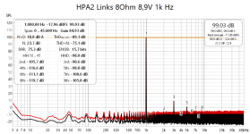
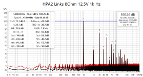
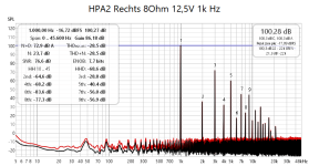
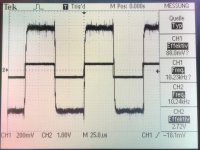
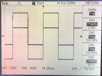
I started with a dummy load of 8Ohm (2x 4Ohm 100W resistors head sink mounted) and got some realy nice results for 2.8V (~1W) and 8.9V (~10W) ...but then I increased just a bit more (12.5V ~20W) and got substantial higher level of distortion (s. pictures Links=Left, Rechts=Right channel).
I was wondering if I simply overloaded the ADC (E1AC, high voltage input 43Vrms) but even with a voltage divider (10:1) I got the same picture.
Any idea what the root cause might be? Strange that both channels show exactly the same results...
Thank you for any help.
Michael
Using the free time while my Season's holidays I have tried to measure my HPA2 (see my earlier posts in this thread).
I started with a dummy load of 8Ohm (2x 4Ohm 100W resistors head sink mounted) and got some realy nice results for 2.8V (~1W) and 8.9V (~10W) ...but then I increased just a bit more (12.5V ~20W) and got substantial higher level of distortion (s. pictures Links=Left, Rechts=Right channel).
I was wondering if I simply overloaded the ADC (E1AC, high voltage input 43Vrms) but even with a voltage divider (10:1) I got the same picture.
Any idea what the root cause might be? Strange that both channels show exactly the same results...
Thank you for any help.
Michael
Attachments

Hi huelskemper,
its a bit strange; have you checked the power supply caps if they have capacitance? It may be that big ripple on the plus/minus supply for the power stage is too big, therefore the distortion at mid levels.
good luck!
Dieter
its a bit strange; have you checked the power supply caps if they have capacitance? It may be that big ripple on the plus/minus supply for the power stage is too big, therefore the distortion at mid levels.
good luck!
Dieter
Hello Dieter,
thanks for your reply.
I have not measured anything in the amp yet but would expect to see 50Hz+harmonics if the filter caps were flat...stupid?
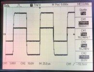
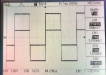
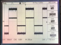
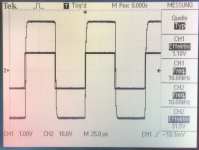
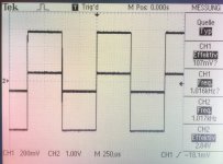
Yesterday I hooked up the amp to a signal generator and fed it with 1kHz and 10kHz square waves at approx 2.8V and 30V...looks really not bad (despite the higher noise level on the right channel for low input, I used the RCA input, normally only XLR).
Quite puzzled....
Best regards
Michael
thanks for your reply.
I have not measured anything in the amp yet but would expect to see 50Hz+harmonics if the filter caps were flat...stupid?
Yesterday I hooked up the amp to a signal generator and fed it with 1kHz and 10kHz square waves at approx 2.8V and 30V...looks really not bad (despite the higher noise level on the right channel for low input, I used the RCA input, normally only XLR).
Quite puzzled....
Best regards
Michael
Attachments
-
 HPA2_R_SquareWave_10kHz_30V_20240102_redux.jpg197.8 KB · Views: 54
 -
 HPA2_R_SquareWave_10kHz_2.72V_20240102_redux.jpg175.9 KB · Views: 55
 -
 HPA2_R_SquareWave_1kHz_30V_20240102_redux.jpg171.9 KB · Views: 56
 -
 HPA2_R_SquareWave_1kHz_2.85V_20240102_redux.jpg163.5 KB · Views: 51
 -
 HPA2_L_SquareWave_10kHz_30V_20240102_redux.jpg122.2 KB · Views: 55
 -
 HPA2_L_SquareWave_10kHz_2.85V_20240102_redux.jpg193 KB · Views: 47
 -
 HPA2_L_SquareWave_1kHz_30V_20240102_redux.jpg148.5 KB · Views: 55
 -
 HPA2_L_SquareWave_1kHz_2.85V_20240102_redux.jpg204.6 KB · Views: 60
Hello,
I called Sun Audio (former German ML distributor) to get some feedback and decided to drop the amp for thorough analysis...not enough time to dive into it momentarily.
Will share the result.
Thanks
Michael
I called Sun Audio (former German ML distributor) to get some feedback and decided to drop the amp for thorough analysis...not enough time to dive into it momentarily.
Will share the result.
Thanks
Michael
Hello everybody,
sorry for the late update.
Sun Audio did a quick job (about one week): Everything working fine (so my test setup was flawed), but they recommended to replace several small electrolytic and film caps as well as some resistors. No need to replace the big supply caps.
Amp is working but now with increased confidence that it should be good for a long time.
Best regards
Michael
Hi Michael,
I would be interested about the price they charged; moreover could you please tell in more detail which caps and resistors should be replaced?
Thanks in advance
Dieter
I would be interested about the price they charged; moreover could you please tell in more detail which caps and resistors should be replaced?
Thanks in advance
Dieter
Hello Dieter,
sure.
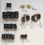
On the picture you can find the parts I got in a plastic bag...but Mr. Krauspenhaar (Sun Audio) informed me that there have been some updates to the circuitry and he used "more modern components of better spec".
Below is from the invoice (translated):
Status:
Damaged PCB GND trace right channel input (...that was actually me hooking up a signal generator to the RCA input while keeping the XLR connected to the low-ohmic pre-amp 🙁 )
High frequency noise on regulated supply lines (both channels)
Several damaged or failed capacitors
Several damaged power resistors
Repair actions:
Repair input right channel
Replacement all electrolytic capacitors in both audio channels
Replacement potentially failing film capacitors in both audio channels
Replacement damaged power resistors in both audio channels
Update circuitry
Adjustment regulated supply voltages pos./neg.
Adjustment bias currents left/right
Quality control (measurements and listening)
He also mentioned that the decoupling foam between the heat sinks and the housings have eroded (changed from froam to tar like consistency). Therefore housing and heat sinks have been cleaned and new foam applied.
Full service was around 800EUR (incl. 19% VAT).
Best regards
Michael
sure.
On the picture you can find the parts I got in a plastic bag...but Mr. Krauspenhaar (Sun Audio) informed me that there have been some updates to the circuitry and he used "more modern components of better spec".
Below is from the invoice (translated):
Status:
Damaged PCB GND trace right channel input (...that was actually me hooking up a signal generator to the RCA input while keeping the XLR connected to the low-ohmic pre-amp 🙁 )
High frequency noise on regulated supply lines (both channels)
Several damaged or failed capacitors
Several damaged power resistors
Repair actions:
Repair input right channel
Replacement all electrolytic capacitors in both audio channels
Replacement potentially failing film capacitors in both audio channels
Replacement damaged power resistors in both audio channels
Update circuitry
Adjustment regulated supply voltages pos./neg.
Adjustment bias currents left/right
Quality control (measurements and listening)
He also mentioned that the decoupling foam between the heat sinks and the housings have eroded (changed from froam to tar like consistency). Therefore housing and heat sinks have been cleaned and new foam applied.
Full service was around 800EUR (incl. 19% VAT).
Best regards
Michael
Attachments
Hi Michael,
thank you for the detailed info; all the electrolytic caps look fine for me - not bloated or similar. Have you checked the capacitance of some of them?
I learned also that Sun Audio is no longer the German representant of ML.
Any more info about "some updates to the circuitry"
best regards
Dieter
thank you for the detailed info; all the electrolytic caps look fine for me - not bloated or similar. Have you checked the capacitance of some of them?
I learned also that Sun Audio is no longer the German representant of ML.
Any more info about "some updates to the circuitry"
best regards
Dieter
Hello Dieter,
you are right: the HPA2 was operating w/o problems. So no need for repair...but recommended maintenance after more than 20 years of operation.
Sun Audio has been for a log time German ML representative (and for all other Madrigal brands) but Harman stopped collaboration when they centralized their distribution and service network (2018/19?). The positive effect: They know the classical ML (and Proceed) stuff, have all the service information, still a lot os components and are open now to also provice support for products not imported by them (my HPA2 was sold in Sweden).
The "circuit updates" have been recommended by Madrigal while the product (market) lifetime. Unfortunately no details known to me...I also do not know which components have been changed because of these updates and which were critical with respect to potential failure.
I measured all components:
Best regards
Michael
you are right: the HPA2 was operating w/o problems. So no need for repair...but recommended maintenance after more than 20 years of operation.
Sun Audio has been for a log time German ML representative (and for all other Madrigal brands) but Harman stopped collaboration when they centralized their distribution and service network (2018/19?). The positive effect: They know the classical ML (and Proceed) stuff, have all the service information, still a lot os components and are open now to also provice support for products not imported by them (my HPA2 was sold in Sweden).
The "circuit updates" have been recommended by Madrigal while the product (market) lifetime. Unfortunately no details known to me...I also do not know which components have been changed because of these updates and which were critical with respect to potential failure.
I measured all components:
- 10nF film caps (yellow) seem to be ok
- 47uF 160V seem to be ok
- 68uF 63V seem to be ok
- 68uF 100V: 2 measure in the nF range, 2 show 4-5% loss --> NOK
- 470uF 16V seem to be ok
- 10uF 50V capacity seems to be ok but 4-5% loss --> NOK
- Resistors 2k74 || 8k66 (2k08) measure all slightly higher (2k11) but show signs of thermal stress (white plastic pin sleeves show black tops)
Best regards
Michael
- Home
- Amplifiers
- Solid State
- Mark Levinson 431 schematics needed