Nehoray,
Lets do some calculation.
Your amp has a measured noise of ca -84dB referred to 1Watt output in 8R.
1 watt in 8R means a voltage of 2.83V rms.
-84dB below means therefore 178uV.
Dividing this 178uV by sqrt(20.000Hz) = 1.26uV/rtHz at the amp’s output.
Compare this to the 0.29nV/rtHz that those 5R resistors are producing, and you see that it is completely insignificant.
Hans

Thank you Hans
It's very very kind of you
BTW
Does any one knows who is the designer of the 33H ???
It's very very kind of you
BTW
Does any one knows who is the designer of the 33H ???
Do the 33H show the poor quality of e.g. compressed youtube music videos?
Or is it the other way;-?
Or is it the other way;-?
Well actually no.
Compressed music by YouTube depends on the sound quality that it was uploaded.
My 33H sound better than ever since it's designed as capacitorless design in the signal all the electrolytic capacitors was chosen by the Ultra lowest ESR in some places I even increased the value of the capacitance
All the diode bridges upgraded to ultrafast soft recovery
Power supply resistor was upgraded to non inductive ayrton-perry wirewond resistors
The emmiter resistors was upgraded to vishay mills non magnetic and non inductive ayrton-perry.
All the fasteners screws and nuts that carrying current was replaced from brass to tellerium copper.
So as you can see it was an investment that paid off since it sound amazing but all this modifications related to the power supplies
Sometimes people try to modify an audio gear putting better parts in the signal path and destroy its magic
That's why I didn't beside the emmiter resistors
However I have started this thread since the amplifiers don't have warmth like the ML27 for example.
So I was looking deeper and the only difference that I saw is that all the levinsons beside the 33 and the 33H uses RN65 in the base of the transistors
But the 33 and the 33H uses different resistors
TF-20 silver palladium resistors
Silver do not have warmth as copper or cr-ni
But Hans puts out that this in not the point to look for...
You´re a lucky guy with your 33H.
There is one thing you could improve and that´s the power supply.
ML always had a bit of a problem in designing proper stabilized power supplies, the 33H is no exception.
To improve some on that, they chose the complex way of generating a clean 60Hz power supply to feed the voltage stabilizer.
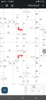
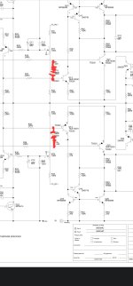
With some simple changes, both the power supply rejection ratio and the output impedance can be improved, see attachment from red to blue.
Whether this has any effect on sound perception, I've no idea.
Hans
There is one thing you could improve and that´s the power supply.
ML always had a bit of a problem in designing proper stabilized power supplies, the 33H is no exception.
To improve some on that, they chose the complex way of generating a clean 60Hz power supply to feed the voltage stabilizer.
With some simple changes, both the power supply rejection ratio and the output impedance can be improved, see attachment from red to blue.
Whether this has any effect on sound perception, I've no idea.
Hans
Attachments
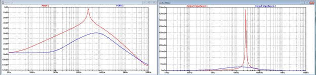

It could be that this helps to get a warmer sound, because the power supply has the tendency to slightly oscillate at 20kHz.
Hans
Hans
Sorry Hans
But I forgot to mention
There are few revisions of the voltage regulation board
Mine has instead of those 4 resistors RN65 10R
Mine has 4 resistors of metal oxide 20R each
How does those values influence the schematic that you have send ?
But I forgot to mention
There are few revisions of the voltage regulation board
Mine has instead of those 4 resistors RN65 10R
Mine has 4 resistors of metal oxide 20R each
How does those values influence the schematic that you have send ?
Attachments
You are right, I overlooked this, but this was already included in my sim, a 10R (20//20) resistor instead of 5R (10//10), see the circuit diagrams I sent you.
So what you have is O.K.
Hans
So what you have is O.K.
Hans
Assuming that an audiophile would not connect his devices with solder, and thus would not tolerate much solder inside his chosen devices, a suggestion: De-solder the entire device and re-solder it. Please solder in such a way - it is about the attention of signal, of current - that you can look through the holes of the board afterwards. But there are more hints, but I don't have to list them ;-)
THIS is THE basis for clean, dynamic, musical sound;-)
Sources and other stuff too;-)
THIS is THE basis for clean, dynamic, musical sound;-)
Sources and other stuff too;-)
Attachments
![DSCN0280[1].JPG](/community/data/attachments/1076/1076630-1a9453d1e89d83de8a10b7ad9c4791fa.jpg?hash=GpRT0eidg9)
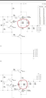
The biggest difference is that Q32 and Q33 are conducting much more current and that R71 and R73 are 2.2 R instead of the 10R (former 5R) that you have.Thank you Hans
Do you see any difference by simulation of the number 33 regulation ??
Parts of the values are different
I know from the ML No.26 ( more than 30 years old but with exactly the same topology) that the current through Q32 and Q33 should either be below 0.5mA or above 10mA.
But I’ll give it a try.
Do you happen to have some info on the pot’s adjustment settings ?
The other difference is that R81 and R82 are replaced by 1.4mA current sources, but I think the effect will be marginal.
Today I won’t be able to do the simulations, but tomorrow I’ll have the time.
Hans
BTW
There are lots of threads regarding the studer 900 regulator which should be great.
Did you made a simulation for this ?
There are lots of threads regarding the studer 900 regulator which should be great.
Did you made a simulation for this ?
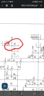
You have the same 330uF, but it is located at a different spot.There is another difference between those 33 and 33H regulators
As you can see at the end of the regulator the 33 uses 330uf
Just look at my sim and see that it was included.
Hans
P.s. don’t know the Studer regulator.
I found some time to compare both.
The 350uF instead of the 150uF at the regulators output adds little to the characteristics, after all it's a regulated power supply.
The changed resistor values at the output do not improve things either with the voltages that the 33H is generating.
One correction to the sims I sent you, these where for wrong supply voltages, after having corrected them for min 61V in and 57,5V out, I noticed that the 470pF caps that I advised to change for 2n2 caps can stay at 470pF.
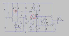
So the only changes to be made are for the 680pF + 249R to be moved from Q13/Q14 to Q21/Q22.
Hans
The 350uF instead of the 150uF at the regulators output adds little to the characteristics, after all it's a regulated power supply.
The changed resistor values at the output do not improve things either with the voltages that the 33H is generating.
One correction to the sims I sent you, these where for wrong supply voltages, after having corrected them for min 61V in and 57,5V out, I noticed that the 470pF caps that I advised to change for 2n2 caps can stay at 470pF.
So the only changes to be made are for the 680pF + 249R to be moved from Q13/Q14 to Q21/Q22.
Hans
Hi folks, I have a question about the 33H, but not related to the electronics yet, I hope someone can answer. One of my 33H amps just died when I turned it one after a month of being turned off and I'd like to remove the heat sinks and see what is wrong. I remember removing them 20 years ago, but I do not recollect how to do it. Can someone guide me through it? I remember removing the sticky rubber pads from under the feet to get at a bolt or two there, but I am not sure now. Thanks!
- Home
- Amplifiers
- Solid State
- Mark Levinson 33H