The working voltage of mark Levinson no.336 current gain board seems to be + - 110V. The working voltage of mark Levinson no.436 current gain board seems to be + - 118V, which is higher than that of No.33 and NO.33H.
That's quit a fortune worth of caps that you have 😀
Repair of this beast must be another nightmare.
Hans
What you showed is the protection circuitry.
Here is the soft start part, not that it helps a lot, but anyhow.
Hans
.
This circuitry was only to limit the surge current at switch on.
Has nothing to do with the soft start of the amplifier.
Hans
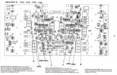
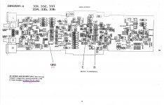
What you can see in the (very complex) input circuitry, is that everything is DC coupled, and that a servo with a LT1097 regulates the output offset to zero.
There are two relays, K1 to shorten the input and K2 to switch the servo's function as integrator to a gain of 1x.
But another relay not visible here should slowly release the output bias current, just as shown in the 33.
But since all is processed with a Field Programmabe Array, it's very hard to tell what sequence is followed.
There is one tip that I could give: the regulated voltages V+ and V- should be always within 100mV to let the soft start work properly and prevent pops.
If not, there are pots to adjust.
You have the schematic of this regulated power supply part, so it makes fully sense to check this.
Hans
Thanks Hans. I did some further testing: There are actually two "pops". The most profound is the second one (so the last relays that activates on the Voltage Gain Board, I have to find out which one that is). Also: If a pre-amps connected the pos are significantly more audible.
Our common friend stated that the power up sequence is microprocessor controlled and if some components are out of tolerance the servo could not set the working point. Seems quite complicated to zero in. In any case I did order the relays and although I am not convinced that this will resolve the issue I think that after 20+ years it is worthwhile to do.
Our common friend stated that the power up sequence is microprocessor controlled and if some components are out of tolerance the servo could not set the working point. Seems quite complicated to zero in. In any case I did order the relays and although I am not convinced that this will resolve the issue I think that after 20+ years it is worthwhile to do.
Relays are not very time sensitive parts. They are only sensitive to welding the contacts together if they try to break 25000uf*110 v energy into a shorted output transistor or speaker. That only applies to speaker disconnect relays. Sometimes the contacts oxidize where the music is supposed to flow through and the music stops there. I told you previously replacing your relays is waste of time & money. You need to look at that power supply balance within 100 mv as Mr. Polak said in post 43.
If that is not the problem I'd be tempted to replace K1 & K2 with LDR's. Would take some engineering to get the series LED resistor right to work instead of the coils not shown on the voltage gain print.
If that is not the problem I'd be tempted to replace K1 & K2 with LDR's. Would take some engineering to get the series LED resistor right to work instead of the coils not shown on the voltage gain print.
Last edited:
Thanks for your feedback. I agree with you that there is only an outside chance that the relays are the culprit: The "pop" noise is on both channels, more or less identical. I did a tentative check of the supply voltage (tentative because the amp was still cold). Both channels, both sides( positive and negative) showed 113V DC. Not sure if this is the correct rating but it seems that supply voltage variation is not the issue. I will check again once the amp has warmed up. Not sure where I can go from here. Worst case I am going to live with it...
Yes, I did however I had no opportunity so far to let it warm up for 2 hrs, as recommended. After 15 min, the voltage was 113.7 both channels, both sides (positive and negative)
...and if I am not mistaken (perhaps you know) these voltages are adjusted with R110 and R153 on the Current Gain board. Correct?
Well, if that is not the problem, then changing the popping relay to a LDR is a possibility. You could look on the schematics for "rel-con" to find out what the drive voltage is. Or you could look at the label on the relays.Yes, I did however I had no opportunity so far to let it warm up for 2 hrs, as recommended. After 15 min, the voltage was 113.7 both channels, both sides (positive and negative)
In stock at newark.com is the NSL-32SR2 LDR optocoupler, https://www.newark.com/advanced-photonix/nsl-32sr2/optocoupler-resistor-2000v/dp/71C0279
40 ohm on, $3.94 . 20 ma design drive current. 5 ms transition time, which can be slowed even more with a capacitor across the led input if necessary.
You would have to remove the relay of course.
To calculate series resistor for the LED, drive voltage V-2.2/.02ma=R
Madrigal doesn't label whether they are using the NC or NO contact of the relay. Usually the contact farthest away from the coil is the NC and the closest in the NO. The NSL-32SR2 acts like a NO contact, on when current flows. If Madrigal used the NC contact then you would have to change polarity of the drive current with a transistor and another resistor for the base drive. Some power supply more reasonable than 118 v would cut the cost of the transistor necessary.
Last edited:
Great - Thanks! Meanwhile I warmed up the unit and I confirmed +/- 115V DC on both channels. When the amp is cold it starts at around 113V and reaches 115V after warm up. Cold or warm, this has no impact on the "pop" noise.
@indianajo: I will look into the LDR option. Thanks! But before I do so I want to investigate the fact that the popping noise is significantly louder with a pre-amp attached.
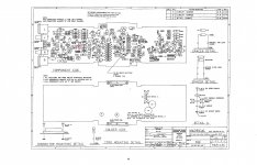
@levinson mark: Reference "Diagram A, DC Offset Adjustment" (lower left corner comment): Shouldn't the adjustment be to <10mV and not to >10mV?
If the preamp was putting out DC voltage, even 50 mv, then the zero to 50 mv step would be amplified to huge volume.@indianajo: I will look into the LDR option. Thanks! But before I do so I want to investigate the fact that the popping noise is significantly louder with a pre-amp attached.
If the "ground" the K1 shorts the input at startup does not equal the voltage on the RCA input ring, than that DC voltage would be amplified as a high frequency step when the relay opens.
Last edited:
...and if I am not mistaken (perhaps you know) these voltages are adjusted with R110 and R153 on the Current Gain board. Correct?
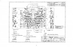
Yes, that's correct, they are 10K pots called VR6 and VR4 in diagram B.
The other two 500R pots VR5 and and VR3 are for setting the bias in the output stage of the reg. power supply.
Measuring across R135 and R170, you should set this voltage to 2.1Volt, or in absolute value on one side 112.9 Volt and the other side 115 Volt.
On diagram B I also see a 200R pot, called VR2 but I fail to find this in the circuit diagram, so maybe some difference between various models.
R72 or pot VR1 on diagram A is to adjust the offset voltage between speaker terminals, although I don't understand why this is needed with the servo U1, the LT1097.
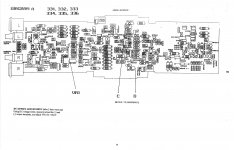
Looking at the protection board, you see that when relay K1 opens, there is a certain time delay for activating one relay after the other.
In successive order: First comes VG Bias, then VG Servo, Drive line, Fet short, Output short and Input short, with resp 100R, 10K. 20K, 30K 100K and 200K, all connected to a 22uF cap.
When K1 shortens, all mentioned relay signals are released in reverse order with 100k,68K,30k, 10k, 5k, and 10R.
So there is a small chance that one of the 22uF caps is malfunctioning, leading to a wrong switch moment !
I suppose this K1 is the one that switches when going from standby to operational and vice versa.
The fact that you hear pops when changing from one state to another, can only mean that K1 is functioning.
That the pops are louder with the preamp connected is not that strange, because the input is completely DC coupled.
Shortening the input will probably give the same effect.
Hans
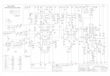
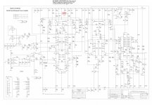
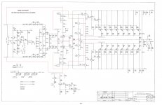
Mark Levinson NO.333 current gain board Schematic.
That's great, and indeed it is the same as all the other ML models with the Fet for soft start, output protection and soft clipping cicuitry.
Hans
- Home
- Amplifiers
- Solid State
- Mark Levinson 333 does not power up