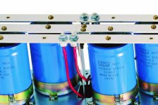
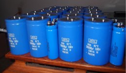
@indianajo: Thanks! I am sceptic about the CDE caps but those were the only caps available re ratings and mechanical fit. Are you familiar with the PS circuit of Mark Levinson 3 series amps? I can not get hold of the schematics and the two bridge rectifier used (apparently connected to these caps) each channel are rated 400V/35A (International Rectifier) seem to be ok (I was only able so far to do a quick check to see if they are shorted). These are pretty pricey - checking online I can find equally rated rectifiers from Mouser or Digital-key significantly cheaper. Any reason to stick with the original brand?
Rectifiers rarely fail, but a shorted load cap can burn one. Rectifiers are easily checked with a $30 DVM. You don't mention what your quick check was. Sometimes you have to disconnect the load to get an open circuit reading backwards. But the screw terminals of those caps provide an easy disconnect without a soldering iron. Mark plus & minus rectifier wires with scotch tape & sharpie, then disconnect. If the rectifiers have push on female flag terminals, even easier. You put the meter probes between "-" and AC (wiggle terminal) and then between "+" and wiggle terminal. .7 v forwards 9999 backwards.
IR has gotten out of the commodity part business. Whatever brand newark digikey or mouser carries in 35 A 400 v bridges should be fine. Make sure heat sink on bottom (usual) is the same of any replacement part or arrange another style heat sink.
IR has gotten out of the commodity part business. Whatever brand newark digikey or mouser carries in 35 A 400 v bridges should be fine. Make sure heat sink on bottom (usual) is the same of any replacement part or arrange another style heat sink.
Last edited:
Thanks. I am hesitant to power up the unit without the caps installed (will arrive Monday). So what I did was a quick resistance check of each diode within the bridge. Not at all sufficient but at least I wanted to rule out a direct short. They have push on female connectors so replacement is easy. I think I am going to order new ones for peace of mind. I found Fairchild brand at Digital-key. Pretty inexpensive. I was told by another lister that the voltage across the caps should be around DC 112-115V
Another possible cause of premature failure of the previous cap would have been backwards polarity. Previous installer could have installed a cap backwards. Make sure + terminal of each rectifier goes to + terminal of each cap. An interruption of the job could have led to a costly mistake. I mark the boards or wires with plus where I replace e-caps. Scotch tape looped over a wire makes a cheap label when marked by a sharpie.
Thanks. I am hesitant to power up the unit without the caps installed (will arrive Monday). So what I did was a quick resistance check of each diode within the bridge. Not at all sufficient but at least I wanted to rule out a direct short. They have push on female connectors so replacement is easy. I think I am going to order new ones for peace of mind. I found Fairchild brand at Digital-key. Pretty inexpensive. I was told by another lister that the voltage across the caps should be around DC 112-115V
What about the ML service point, did they respond in any responsible way ?
To be honest, I thought the same as Indianajo but this can never be proven.
Hans
The caps were installed correct, they worked for 7 months no problem. The wires to the caps are color-coded which also helps. Other than failed bridge rectifier I have no clue what else could have caused this. Dimitri stated that he had a case like that where the power outlet had a bad neutral.
The ML Service Station did not get back to me (yet).
Any other suggestion?
The ML Service Station did not get back to me (yet).
Any other suggestion?
What I meant is that the service guy could have accidently mounted the cap in reverse position, fired the amp up, immediately noticed his error because of a humming transformer and rotated the cap.
So what you finally got was correctly mounted, but a mishap like that is killing for caps, shortening their lifes and leading to exactly what you experienced.
Very bad to hear that the service station tries to evade their responsibility.
At least they could have offered you a new cap for 50% or some other gesture showing their good will.
Hans
Ah ok. That is possible. I just informed the service people a few days ago so I am still holding judgement and hope that they eventually come through.
Interesting enough, I noticed some dried up electrolyte around the vent hole on one cap of the other channel. Not as bad as the other cap, but still...
Interesting enough, I noticed some dried up electrolyte around the vent hole on one cap of the other channel. Not as bad as the other cap, but still...
That’s what happens when connected the wrong way.
An immediate heat builds up because of some sort of short circuit resulting in sputtering.
When you have an old cap, just try it, real fun but protect your eyes.
Hans
An immediate heat builds up because of some sort of short circuit resulting in sputtering.
When you have an old cap, just try it, real fun but protect your eyes.
Hans
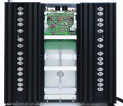
Update: After replacing all four caps and the bridge rectifiers I re-assembled the amp and it seems to work fine again! I still need to test it with my audio system but all indications are good so far.
What still others me is a "popping noise" through the speakers whenever the unit goes from "stand-by" mode to "on" and reverse. I noticed such noise before the caps blew so I don't know if this is by design or if something else is wrong what I could fixed "while I am at it". As far as I can tell, the amp does not have speaker relays and so without schematics I am not sure where to start.
What still others me is a "popping noise" through the speakers whenever the unit goes from "stand-by" mode to "on" and reverse. I noticed such noise before the caps blew so I don't know if this is by design or if something else is wrong what I could fixed "while I am at it". As far as I can tell, the amp does not have speaker relays and so without schematics I am not sure where to start.
There are internal relays used for steering standby and soft start and shut off.
Part of it is visible in the circuit diagram that you already have.
But it is not easy to find your way.
Hans
Part of it is visible in the circuit diagram that you already have.
But it is not easy to find your way.
Hans
Yes Hans, I just found them on the Voltage Gain Board (I was not looking there). 3 per channel. I am just not sure if it makes sense to replace them - can they be the culprit?
A pop when a relay pulls in could be a difference between DC voltages on the two sides of the contact. I'd look at that first, instead of changing the relay. Use Pamona grabbers to hold on to some component leads so you don't mess the reading up with probe slips. DVM is fine for this check. In general don't use two hands at all when probing the amp with the power on. Especially one with 100 v rails. Any voltage over 25 from one hand to the other can stop your heart. (Sometimes)
Can't help much more without a link to the schematic diagram.
Can't help much more without a link to the schematic diagram.
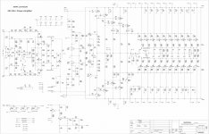
K3 is controlled by "Rel Con" which is not on this page. K3 applies rail power to the driver transistors Q33 & Q44 when pulled in.
K1 grounds the input going to U2 both sides. Coil not shown.
K2 shorts a timing capacitor to feedback of U1 when pulled in. Coil not shown.
I suspect relay control is a power up silence circuit, possibly at this price point also a AC off silence circuit. Rel Con is probably a timer somewhere.
This is going to be difficult to debug. I found at work that switching a high gain input from one source to another leads to huge voltage pops. A relay is the wrong part for the job. People now use LDRs to switch from one thing to another, which change state over 100 ms and don't cause a pop. LDR were just beginning to be used about 1964 and Wurlitzer was building their own; they weren't commercially available yet. In 1964 the light source was an incandescent bulb, which was its own maintenance hassle. Now they use LED's with longer lives than tungsten filament.
Last edited:
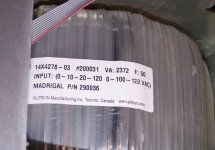
The working voltage of mark Levinson no.336 current gain board seems to be + - 110V. The working voltage of mark Levinson no.436 current gain board seems to be + - 118V, which is higher than that of No.33 and NO.33H.
Attachments
-
 4.Mark-Levinson NO.33.jpg320.1 KB · Views: 338
 -
 MARK LEVINSON No.33 CAPACITORS.jpg167.2 KB · Views: 357
 -
 1.Mark-Levinson NO.33.jpg726.9 KB · Views: 383
 -
 6.Mark-Levinson NO.33.jpg534.2 KB · Views: 390
 -
 2.Mark-Levinson NO.33.jpg483.5 KB · Views: 433
 -
 Mark Levinson NO.33H.jpg870.2 KB · Views: 432
 -
 NO.336 www.plitron.com.jpg184.3 KB · Views: 356
 -
 Plitron.png81.3 KB · Views: 273
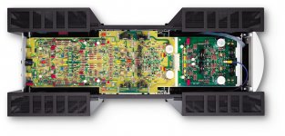
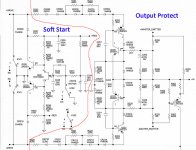
This 33 output section is practically just a bigger ML No 2x.x with exactly the same soft start and output protection, see image taken from the 33.
The only thing that is added are three relays that come into action when DC is detected on the output or in case of overheating.
The ML No 2x.x numbers shut off their mains supply instead.
Also the soft limiting of the signal, the bias setting and everything else is the same as in the older ML 2x.x amps, amazing.
Agosto, I'll compare this to your 333 amp to see what parallels can be found.
Hans
Attachments
- Home
- Amplifiers
- Solid State
- Mark Levinson 333 does not power up