Hello Dave.With current amp you have to flatten the impedance peak at resonance.
dave
12p is good at microdetails.
How about 7p and 10p?

DDR? I found it. "downward dynamic range"7p har en problematisk topp, A10p har mer DDR än A12p.
dave
Last edited:
Jumping on this one a few years on. But did you ever test, or have an opinion on, which approximate source impedance these drivers prefer? For example, for Lowthers, you have earlier stated they/some of them prefer a finite SI, approximately 10 ohms.I own most of the MarkAudiio drivers, and they are quite neutral and easy to
drive, which opens up a whole world of prospective amplifiers. 5 - 20 watt
single-ended Class A is my choice if you want to "sweeten them up".
They behave themselves nicely with CS amps, which bump the bass up
a bit with sealed or TL enclosures. Of the transmission lines, the old Bailey
designs are favorites, but that might reflect the fact that I cut my teeth
on them at ESS when I was 21.

I own 12Ps in poorly built Super Pencils at the moment.
Regards,
Andy
Last edited by a moderator:
….but that might reflect the fact that I cut my teeth
on them at ESS when I was 21.
I was just a bit younger and it was the (directly) Bailey inspired Radford S90 that i played with.
We can do much better nowadays.
And speaking of A12s, the ACAmini you made me is doing a stellar job driving a pair of A12pw in parallel. Thak you very much.
dave
I own 12Ps in poorly built Super Pencils at the moment.
With Pensils the back is removable to allow for different damping densities.amounts which can pretty much allow adjustment for whatever amp you are using.
These drivers have fairly low Qms which tends to make them more tolerant of a wide range of Rout amplifiers, and in the case of the Pensil damping to dial the rest in.
dave
I have built several speakers using current drive. They work great. I use a Linkwitz transform to produce the low end response I want. It works perfectly with woofers, midranges and tweeters all the same. You simply measure the Q and resonant frequency of the driver in the box and then use one of the available calculators to produce the filter needed to get the Q and resonant frequency you desire. I use this method to produce the crossover high pass filter for any driver. The miniDSP website has a filter spreadsheet with a Linkwitz filter calculator page. The filter can then be loaded into a miniDSP or equalizerAPO on a PC or JRiver software or many other devices that implement a biquad filter. If you have lots of money, time and skill you can implement it using analog components at the preamp level. I would mount that driver at the center of the square face of a sealed half cube shape box, stuffed with fiberglass batting or dense lambs wool. The volume of the box can be small, targeting a Q of 0.8 with voltage drive sealed box calculator. The displacement is the only thing that determines the output of a sealed box system. Cone area times Xmax. If you want more SPL at low frequencies than the displacement of that driver provides, adding a second woofer in a similar box will do that perfectly and give you many options for dealing with floor bounce nulls because you have two woofers at different heights off the floor. When you compare the cost of building small sealed boxes with other options, you will immediately see the benefit.
Last edited:
I hate the 30 minute editing timeout. After looking at the Markaudio website I notice that they don't bother to specify the Xmax for that driver ( the linear operating range). That is very telling. I expect it is near zero if they are not willing to write it down. This is likely how they achieve the high SPL / watt of this driver. So in a sealed box this is a midrange or good for some bass when using a vented enclosure to keep the excursions near zero at the box resonance. With anything beyond something like 1 or 2 mm of travel, I predict the distortion of this driver will be rapidly pushing above 1% and more. That level of performance will make lots of people happy, but it's not high fidelity. Maybe some of the folks who own these can post a measurement of distortion with one watt of drive power across the frequency range.
| Revc | 7.00 Ohm |
| F0 | 42.149 Hz |
| Sd | 177.410 cm² |
| Vas | 43.060 Ltr |
| CMS | 1.369 m M/N |
| MMD | 9.188 g |
| MMS | 10.217 g |
| BL | 7.540 T.M |
| QMS | 1.981 |
| QES | 0.333 |
| QTS | 0.285 |
| LeVc | 53.952 uH |
| No | 0.936 % |
| SPL0 | 91.730 dB |
Last edited:
From page 3 of the data sheet i got from Mark:
dave
The recommended Max usable excursion = 5.4mm X 1 way (non linear bass load)
dave
I saw that. Max usable is the mechanical limit to avoid damage, not the linear operating range. Most driver makers specify both. The max usable is often two or three times the linear range. There is no Xmax linear operating range specified. A simple distortion measurement vs. frequency with a quality microphone will tell the real story. In a sealed box below 150 Hz, I would expect the distortion to rise rapidly with one watt of drive. I don't have one of these or I would test it myself. As this is "do it yourself Audio" the fun is left up to the reader.
Last edited by a moderator:
A tinkerers amp, for a tinkerers driver category. I think that makes me a tinkerer.It's all over the map. Mostly I made networks that flattened out the response, but it's easy enough to adjust the loading on a current source amplifier (or put impededances in series with a voltage source) and see what you get.
Exciting stuff.
I’ll start with measurements, then try adjusting load, and based on that possibly experiment with networks. Unless I risk violating the super secret patents of Transparent cable that is

Anyways, gotta build an amp first. Maybe Christmas time tinkering then.
Thank you!
Regards,
Andy
I did found some test results of a Mark Audio driver at HiFi Compass. The Alpair 10P The measurements include Harmonic Distortion, HD Frequency Response plots. I had forgot about this site. There are test results for many drivers posted, including a new metal cone from Purifi. https://hificompass.com/en/speakers/measurements/markaudio/markaudio-alpair-10p The measurement for the metal cone looks like one would expect. The paper cone has a rise in distortion mid band at 550Hz for some reason. Results from one driver, so who knows.


Last edited:
Well a couple of weeks on, I gotta say the F2(J in this case) and 12Ps is a match made in heaven. Mid range is tamed, the transistor radio tendencies are gone, highs are more extended, and bass is just moooooore.
So far everyone that has listened to it didn’t wanna stop.
And that is before any tinkering.
Simply love it.
Regards,
Andy
Attachments
I agree, it is a real hassle. But thank you for the feedback! PS: you probably know, but the F2 is a current source, so some of the things I commented on are parallell to Papas article on the subject.That is a thing of beauty. Nice job. So good when it sounds right. I've been working on designing a box for an amplifier this week, and deciding on the layout of the boards and connectors in the box is my least favorite thing to do.
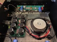
For this amp, I tried Pa’s First Watt layout. Boards are not made by me. I wanted to see how his layout works, since it contradicts some of my audiophoolery assumptions. And it works very good!! Though, the tranny buzzes, so a new one is being made as we speak. Will try a dc blocker anyways and hopefully get a refund if that doesn’t work.
May I ask what amp you are building?
Wrt tinkering, that statement was made with loading the output and perhaps building a network to even out frequency response. But right now it sounds magic, I might leave it like this for a while 🙂
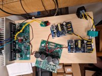
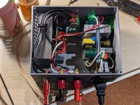
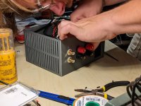
I bought the Douglas Self Load Invariant kit a while back and I decided to build it as two mono-block amps with switching supplies for light weight. I will mod it to be a transconductance amp as well. Mr Self wasn't real keen on the idea when I asked him about it, but I tried the mod with the spice model and it looks fine. I was inspired by my son 3D printing a case for his amplifier build last month, so I'm trying to shoe horn the Self boards into the size case I can print with my printer. Here's a picture of the Self boards on plywood and a few pics of my son's LM3886 amp in the printed case. My case will be hitting the limits of the printer at 250 mm x 200 mm as the heat sink is 250 mm long.May I ask what amp you are building?
Wrt tinkering, that statement was made with loading the output and perhaps building a network to even out frequency response. But right now it sounds magic, I might leave it like this for a while 🙂
Attachments
- Home
- Loudspeakers
- Full Range
- Mark Audio Alpair 12P with current drive