Please reread paragraph 1 in Post #1 of this thread. The last sentence states:
" A stuffing density of 0.75 lb-ft3 is placed in the top half of the box."
I suggest that you redo the stuffing for best results.
" A stuffing density of 0.75 lb-ft3 is placed in the top half of the box."
I suggest that you redo the stuffing for best results.
I apologize, I did read that paragraph multiple times, I just wasn't comprehending it I guess.
I was reading it as "0.75 lbs of stuffing per cubic foot of box space, placed in the upper half of the box".
Now I see that that's not what you meant, and it makes a big difference in total amount of stuffing placed.
I'll go back and pull out some of the fill, and fluff up what's left.
Thanks for clarifying. 😀
I read Jim added some thin sound absorbing material on the internal surface. Does it has to cover the whole chamber? or just lower part of the chamber? Or, it's optional?
I didn't add any thin sound absorbing material to my Mark Audio projects but I have added a layer of thin Sonic Barrier to some of my projects. On those prototypes I layer (single thickness) the insides of the enclosure and it adds damping to the speaker. A noticeable deadening when you do the knock test on the outside of the box. One of the materials I have used is:
Sonic Barrier Lightweight Vinyl Sound Damping Sheet 27" x 40"
Similar absorbing sheets can be employed if you wish. While it is not meant to take the place of the volume damping with polyfill, it is useful in many cases.
Sonic Barrier Lightweight Vinyl Sound Damping Sheet 27" x 40"
Similar absorbing sheets can be employed if you wish. While it is not meant to take the place of the volume damping with polyfill, it is useful in many cases.
Last edited:
Thanks Jim. Should we add this kind of sheet? We have something similar for car. I know people use this to modify Klipsch Horn.
Not sure about MLTL design need the resonance of the lower part of the box.
Besides, i found your drawing in Frugal Phile but it's taller and the Cross section area is slightly smaller. Which one do you prefer?
If i add the spike or the base for the speaker, does it affect the height of the bass port? Sorry for so many questions. I tried to find the drawing here but it is not available.
Just for certain if you are building a speaker please use the description in this thread for reference just to be sure that you have the straight facts. The dimensions in message #1 of this thread are internal dimensions so add-on spikes or base plates which add to the inner dimensions and the enclosure wall thicknesses to achieve the total external dimensions of the speaker. But the relative driver and port locations are not changed and are invariant per the inner dimensions of the working portion of the enclosure as spec'ed in message #1.
Adding the thin (0.05" thick) absorbing sheet material will help to add damping to the walls of enclosure structure and would be warranted if you select light weight enclosure material. For good quality plywood or MDF it is probably not needed.
Adding the thin (0.05" thick) absorbing sheet material will help to add damping to the walls of enclosure structure and would be warranted if you select light weight enclosure material. For good quality plywood or MDF it is probably not needed.
Last edited:
thanks Jim.
Just for my understanding, i want to ask the followings:
I calculated the driver is actually lying at 20% length of the total height of the internal dimension. 8inches/40inches.
You also mentioned "The driver is located one third of a wavelength (given the length of the line) down from the top of the enclosure in each case.' If it's 33%, it's around 13inches. Does it mean if the driver can locate 8inches to 13inches below the top?
I would stick to 8inches of course but wanna understand how to calculate. Or it has to be done by the simulation?
For the stuffing, how do you make sure it won't touch the back of the driver diaphram?
One last thing, i got the MAOP 10, i suppose i can use the same design. I plan to have 6inches x 7.5 inches as suggested by you. If the manufacture added some supportive wooden block at the corner, can i just make it simple to make it larger 6x8inches? What's the acceptable tolerance of the cross section area? I guess the wooden block is very small in cross section area. I guess it's like 1.5cmx1.5cm
polywine,
Let me clear up any confusion on the location of the driver relative to the length of the box. I have two MLTL designs for the Mark Audio Alpair 10.X drivers. My earlier design with the Alpair 10 (or perhaps correctly the 10.1 version) does locate the driver one third wavelength down (from the top of the box). This design yielded a longer enclosure or taller MLTL.
The more recent Alpair 10.3 and 10P MLTL (this thread as detailed in message #1) locates the driver one fifth of the way down the line. This design is the subject of this thread. This MLTL (for the 10.3 and 10P designs) is shorter than the older design for the 10.1 design.
Bottom line is to stick with the design in message #1 above as you are currently using.
For your concern of touching the diaphragm with the stuffing: Normally I don't have that problem. I avoid overstuffing the enclosure and take care while placing the polyfill inside the box. Thus the driver and the polyfill shouldn't be in contact. If they do contact it would be minimal. I suppose that you fashion a mesh cloth cover around the basket of the driver to separate the driver from the polyfill but this isn't needed.
I have not simulated the MAOP 10 unit so I would not assume that my 10.3/10P MLTL can be used with it as is.
If a supportive wood block is placed in the corners of the MLTL, then this may significantly change the cross-sectional area. Hence, the dimensions should be changed to account for the modification. My comment is that if the change is less than 5% area then it likely would not matter.
Last edited:
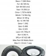
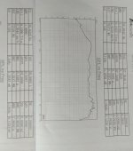
i got the driver today. They have Attached the report and this is different from the website
The actual driver test report Look very similar to Alpair 10gen3 now. Do you think i can use this design?
The actual driver test report Look very similar to Alpair 10gen3 now. Do you think i can use this design?
Attachments
Last edited:
I did not rerun my A10.3/10P simulations but these MAOP 10 drivers are likely within production limits of what to expect between normal A10.3 production units. The change in Vas between the 10.3 and MAOP 10 is a bit less than the change I simulated between A10.3 and A10P units. That difference was just a tweak in the port length (6" for the 10.3 and 5" for the 10P). If I have a chance, I'll fire up my old computer and sim the MAOP 10 numbers. I'll say that you are good to go with your plans.
Last edited:
Hi all,
So I've pulled my drivers and tested them using the Dayton DATS V3.
I'm noticing right away that something is a bit...off.
Either the published specs are wonky, or the DATS isn't measuring correctly. If it's the latter, it very well could be something I'm doing wrong.
Regardless, the F(s) is measuring nowhere near what they publish on the MA site. The DATS is reporting around 41-42Hz (there's some variation I'm not wild about), but the site claims an Fo (is that the same?) of 38.266Hz.
Also, DATS reports a Q(ts) of ~0.396-0.422, whereas MA publishes 0.316.
Now I'm not gonna begin to claim to know enough about any of this to really comprehend the nuances of the various factors, but variations that large seem like they might account for some of the performance issues I'm experiencing with the set I've built using Jim's MLTL design. If he modeled it based on the published specs, and mine aren't operating at those specs, wouldn't that cause it to sound different? Or am I overthinking this?
I will note that these drivers are fairly thoroughly broken-in (60+hrs), so I don't think that's the issue.
Any thoughts appreciated.
-Mike
T/S are curves not scalars. DATS is collapsing the curve at a different place than the factory sw. It is really only good for matching, and, as i understand, it estimates the parameters instead of direct measurement.
dave
dave
I'm not totally sure I follow Dave.
So you're saying that the DATS box isn't really directly measuring the parameters, and isn't very accurate? If that's the case, I need to return this thing, since one of the main reasons I bought it (other than testing these drivers) is so that I can sniff out mystery drivers I pick up from here and there. If it's not going to be giving me good, usable info, I have no need of it.
So you're saying that the DATS box isn't really directly measuring the parameters, and isn't very accurate? If that's the case, I need to return this thing, since one of the main reasons I bought it (other than testing these drivers) is so that I can sniff out mystery drivers I pick up from here and there. If it's not going to be giving me good, usable info, I have no need of it.
Certainly the indirect method is not as accurate as directly measuring them, but mst of the difference is from a different point of collapse.
dave
dave
I gotcha. So direct measurement would be...how?
With a mic? That would get some of the parameters, but not all, right?
With a mic? That would get some of the parameters, but not all, right?
Hi all,
So I've pulled my drivers and tested them using the Dayton DATS V3. I'm noticing right away that something is a bit...off.
Either the published specs are wonky, or the DATS isn't measuring correctly. If it's the latter, it very well could be something I'm doing wrong.
Regardless, the F(s) is measuring nowhere near what they publish on the MA site. The DATS is reporting around 41-42Hz (there's some variation I'm not wild about), but the site claims an Fo (is that the same?) of 38.266Hz.
Rather close then; assuming 41Hz, DATS is giving you a figure only 6.67% from stated; assuming 42Hz, it's 8.9%. That's pretty good. All measurement systems will give different results due to the differing ways they work & how they're taken.
I've just finished measuring 4pr of drivers from 'a company'. No names. They're a major supplier, well known, well regarded, and have impressed me very much indeed. Excellent units, excellent pair-matching, fantastic build, great features. Out of the box, I was getting a 25% deviation in Fzero (Fs) from published. Hammering them with a 20 minute programme of infrasonic sinewaves, as usual, Fs, Qe, Qm, Qt dropped, Vas increased. They're now within 10% of advertised, which is pretty standard production QC tolerance. More of which in a minute.
You have DATS v3; this is the latest version and actually rather good: far more so that the earlier versions. You can adjust the drive level; maximum is 11.4dBu (about 2.883v). You want to see how T/S parameters change with voltage input, as Dave explained above? Go into DATS, open the Impedance Analyser menu, and select the DATS Linearity Test. Change the number of sweeps to 5, and increase the highest level to 11.4dBu. Let it do its thing and take a gander at the results.
T/S parameters also change, sometimes quite significantly, with local climatic conditions (ambient temperature, pressure etc.). For instance, I've measured over 7% Fs deviation in various units from a similar change in centigrade (room temperature).
Unlike a midbass, you can't hammer the MA drivers to full travel with LF sinewaves: they're low-mass wideband drivers, not heavyweight subwoofers and not able to be pushed that hard continually. The long travel is there to handle short-term loads -brief LF dynamic peaks etc. So it will take a while to properly break in the suspensions, which will drop Fs, Q, increase Vas etc.
- Home
- Loudspeakers
- Full Range
- Mark Audio Alpair 10.3/A10p MLTL