You cannot fix the "problem" since it is a result of the circuit design.
Perhaps the op amp in question has degraded and has more input current than it originally had,
and no longer meets the specs for the part. You could try another new, unused sample of the same part and see.
Semiconductors can change their characteristics over time, for various reasons.
Some new parts in DIP packages must even be "baked" in order to meet their specs after long storage times,
like carbon comp resistors, and for similar reasons.
Last edited:
One observation: given that opamp inputs are slightly negative, installed polarity of C701 is correct, but C713 is backwards. Correcting probably won't make much difference.
I think the OPAmp output is supposed to be firmly biased into class A, by design. Of course, I might be wrong - wouldn't be the first time... nor the last.

I prefeer try to add the offset nul balancer already posted by me. It is the natural way to do it.
There's currently a 10pf capacitor there. Would you suggest I cange that? What about the temperature issue that was mentioned? Thanks
Try the 6,8M resistor as suggested (probably the easiest way), or use low input bias current OPAmp like OPA134 (may bring sound improvement as well).
The offset nulling is also a valid solution - you can leave the 10pF capacitor in place.
Or, ignore the offset... it is not that bad. Do one of the above if it gets above 100mV.
The offset nulling is also a valid solution - you can leave the 10pF capacitor in place.
Or, ignore the offset... it is not that bad. Do one of the above if it gets above 100mV.
I dont get whats happened to orignal design. My aim is to not really get it to 0mv but get it to the correct 60mv output. If its a case of replacing the opamp with new ones then thats a lot easier to be fair as I have no idea how all these fixes will affect the sound.
so far I got
1), 6.8M across the negative and pin2 input of opamp
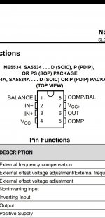
2) trim pot between across pins 1 and 8 of opamp (but what value? and trims has 3 legs, short 2 toegther?)
Looking at it if sound quality is not affected then 6.8m seems easiest and best!
I'm open to other ideas and really greatful for all the help given!!
so far I got
1), 6.8M across the negative and pin2 input of opamp
2) trim pot between across pins 1 and 8 of opamp (but what value? and trims has 3 legs, short 2 toegther?)
Looking at it if sound quality is not affected then 6.8m seems easiest and best!
I'm open to other ideas and really greatful for all the help given!!
Pin 4 to pin 3? of opampBias offset resistor to pin 3, not pin 2!
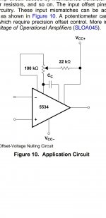
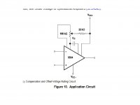
I just did and it also talks about adjusting the offset bias with potentiometer. I'm having a little difficulty understanding the drawing. It shows 2 resistors of different value, one is 100k and other 22k and it doesnt state which pins its connected to.Did you try looking in the 5534 datasheets, page 11?
Attachments
Bias 6.8M resistor should tie between -17V and pin 3 of opamp.Pin 4 to pin 3? of opamp
If you're talking about replacing the opamp and adding an offset pot, we're in a different realm.
OK.........Plan is to order 2 new 5534 (any brand probably TI)
and order 2x 6.8M resistors.
I will fit one opamp first to see difference. If no difference I will try the resistor mod.
and order 2x 6.8M resistors.
I will fit one opamp first to see difference. If no difference I will try the resistor mod.
Not any brand, only the TI brand, and only from a reliable supplier like Mouser or Digikey. No ebay etc.
It's only $1.
It's only $1.
Last edited:
- Home
- Amplifiers
- Solid State
- Marantz PM75 DC Offset