PM6010 Problems
Hi, I have a PM6010 KI and the main fuse has blown. I have tried everything suggested -
Removed and tested ALL transistors, they seem ok.
Tested R801 R802, seem ok.
I switched on and relay did not click off, then small resistors near the back of the board RN01 + RN02 blew.
i changed them and switched on again.
the two large resistors R771 R772 - 10R 3W - got hot VERY quickly, so I replaced these and switched on again, that is when the fuse blew.
Please someone help, I am without music.
RN01 and RN02 feed the base of the power transistors and R771 R772 are on the output.
This means the output is knackered. You really need to change every transistor on both outputs. The smaller idle / bias transistors controlling the output have broken down and when you switch on you are getting thermal run away.
Change Q751 Q753 Q755 Q757 Q759 Q761 Q763 QN01 QN03.
Repeat for the other channel, then when it powers up follow the very important idle bias set up procedure.
Brent
Thanks again Brent you're a star.
I'll order the new parts today. I'm not sure how I did it, the amp was fine until I added two 1000uF Silmics in parallel with the res Caps. They were there when I bought the amp!
Best regards, Lee.
I'll order the new parts today. I'm not sure how I did it, the amp was fine until I added two 1000uF Silmics in parallel with the res Caps. They were there when I bought the amp!
Best regards, Lee.
Hi, I have a blown 66 KI and have proved that the R802 resistor is blown but in trying to do power on testing Q764 burst in to flame! 
Is there any point in trying to repair? Presumably if I try I need to replace all the transistors on this circuit now?
Also could anyone send me a copy of the schematic to neil_withers3@hotmail.com please?
Neil
Is there any point in trying to repair? Presumably if I try I need to replace all the transistors on this circuit now?
Also could anyone send me a copy of the schematic to neil_withers3@hotmail.com please?
Neil
Hi
R802 is a 47 ohm resistor and these do blow over time. They run quite warm and fatigue causes them to go. This resistor supplies voltage to the regulators for the protection circuit. This is why it will have not clicked into operation.
The output transistor blowing is not caused by this resistor so I can only assume you may have slipped and shorted something out
Firstly I would remove Q764 Q762 and Q752 (all on heatsink).
Then power up amp and test for it clicking into operation and working on the left channel.
If all is ok then you can replace these 3 transistors and hope the rest of the circuit is not damaged.
If it blows again then its a full rebuild on that channel as listed earlier for Thomo.
If you decide to scrap it let me know and I may buy it off you as a back up for myself (I have 3 of these in my 5.1 system).
Brent
Please can I have a copy of the schematic for my 66KI sig? Please ? 
I've been looking at various component supplier websites and can't find all the things I want. Can anyone suggest some good websites for capacitors and transistors?
Are there any tried and tested upgrades to the transistors? I have 2SA1265N type at the moment, while I'm changing some I thought I might change them all out.
Also can anyone give me a run down of which capacitors on the board perform what function? I'm trying to decide on replacement capacitors, but there are various different black gates for different jobs and I've confused myself trying to figure out which I need. N type, K type, standard, C type? I don't know!
I guess I've kind of decided that if I'm replacing bits I might as well try to upgrade at the same time !
Regards,
Neil
Firstly look at upgrading the res caps (12000uF 56V Elna for Audio). Also change the TX or add a second, this really doubles the level of this amp.
There are 3 caps that supply the voltage control/pre amp chip, these want upgrading.
Black Gate caps here
Output transistors from here
And here...
Send me an email for a sch + I can send you my latest mods list
Brent
There are 3 caps that supply the voltage control/pre amp chip, these want upgrading.
Black Gate caps here
Output transistors from here
And here...
Send me an email for a sch + I can send you my latest mods list
Brent
I can't find anything bigger than 10000uF on that Hifi Collective site, and to be honest I'm not in the market for paying £140 per capacitor anyway. How much would Elna Silmics cost and where can I get them in 12000uF or bigger, anyone? In fact, where can I get any audio suitable caps that are 12000uF or bigger, I don't want to try these if I can help it!
Are Cornell Dubilier worth a look, or Mallory?
Neil
Are Cornell Dubilier worth a look, or Mallory?
Neil
Stick to good quality caps , this is just as important as the uF. Rather than looking for two big caps like mine (I found them on the forums for sale by chance). Why not use 4 10000uF etc (2 for each rail) Lots of smaller caps is quite ofter a better idea.
I have not tried the Cornell Dubilier or Mallory so can't really comment.
Brent
I have not tried the Cornell Dubilier or Mallory so can't really comment.
Brent
Hi guys.
I fitted 2 15000uF 80v Cornell Dubilier caps in mine and they sounded very good. They defo improved over the Elna 'For Audio'.
I do think though that a bank of smaller Elna Silmics or similar will be better.
Lee.
I fitted 2 15000uF 80v Cornell Dubilier caps in mine and they sounded very good. They defo improved over the Elna 'For Audio'.
I do think though that a bank of smaller Elna Silmics or similar will be better.
Lee.
At that price its worth trying, I no nothing about the Mallory caps so I would say go for the Cerefine (unless you know otherwise).
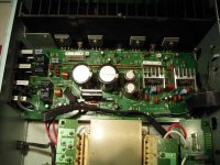
See how mine are mounted! Do it that way. My caps are the size of coke cans and really are over sized. You may be able to get 4 of the ones you're looking at fitted in the same way.
Another option is to fit 2 bigger ones to the rear and some not quite so big in the original place.
Lots to ponder
Brent
chicco_36 said:So,
Which one is better :
2SA1941 or 2SA1265 ?
2SC5198 or 2SC3102 ?
If you can, go for 2SA1943 and 2SC5200, best from Toshiba IMHO.
Chicco
Has anyone tried these transformers? I am a complete novice with electronics but having had a quick look a the specs of the 1943 and 5200 transistors, they are totally different from the standard ones.
I am slightly puzzled given the amount of time and money people here are prepared to spend on replacing caps and stuff, why transistors aren't really mentioned? Surely these little fellas provide the actual amplification? A more linear response from these must provide a significant improvement, and it only takes a glance at the data sheets for the 2SA1265 and the 2SA1943 to see how different their respective responses will be for a given input.
Unfortunately I wouldn't have a clue which ones would be better, but one of you clever people must be able to tell us if we can upgrade the sound by changing the transistors or if the sound would be totally ruined? Are the values of all the discreet passive components chosen specifically to complement the characteristics of a particular transistor?
😕
Neil
Elna For Audio PSU caps for PM66KI
Hi Brent
I have just opened up my Kenwood 3020SE which has a pair of Elna For Audio 10000uF 42v res caps.
I have a PM66KI which I have been modding from your list.
I was thinking of adding these in parallel with the existing res caps (which I snubbered as per your mods list) as I can't find any bazookas like yours
Do you know if they would be OK as I am not sure what voltage the KI runs at?
Kenwood has a massive heatsink and beefy output transistors and looks really neat next to my KI and also a Class A and Class B section. Interesting........
Cheers
Jim
I have a 3020SE its in my dining room. Great amp! May mod mine 
Pop a piccy on here of the internals 😉
The caps are not a high enough voltage My KI runs at 44V.
Kenwood have always used good heatsinks good old proper cast aluminium ones. The Marantz heat sink is actually bigger than you think though, the veins are thin but do effectivley create an updraft. Also the aluminium the transistors sit on is decent + there is partial sinking to the chassis. All the output transistors are on one heatsink in the kenwood too if i remember correctly.
But yes it looks poo in the marantz.
Brent
Pop a piccy on here of the internals 😉
The caps are not a high enough voltage
My KI runs at 44V.Kenwood have always used good heatsinks good old proper cast aluminium ones. The Marantz heat sink is actually bigger than you think though, the veins are thin but do effectivley create an updraft. Also the aluminium the transistors sit on is decent + there is partial sinking to the chassis. All the output transistors are on one heatsink in the kenwood too if i remember correctly.
But yes it looks poo in the marantz.
Brent
Hi Brent
Yes the Kenwood looks much neater and logical as if it was designed from scratch for efficiency. Real macho stuff inside.
You're right about the output transistors, and they are big beasts too.
Will post some pics on here. Now, if I can just find that digital camera and charge the batteries...........
Better make sure I don't fry anything in the amp like I did on my CD63Ki
Cheers
Jim
Hi Everyone,
Hope this is not off topic but after much searching this seems to be the best place to ask. 🙂
I recently repaired my PM44SE amp by replacing some blown output transistors. My question is: does anyone know what value to set the idling current to on the output stage of a PM44SE amp?
The PM44SE has the same circuit as the PM66KI except that some components are different values. I only have a schematic for the PM66KI and it shows R767 & R768 as 0.1 ohm x 2, but on my PM44SE these two resistors are 0.18 ohm x 2. From rowemeister's previous posts I know what idle current setting to use for the PM66KI but because these resistors are different on the PM44SE then I assume the idle current must also be different.
Anyone know?
Thanks, Victor
errr don't know
Did only one channel blow?
If so from cold monitor both chanels for mV and see how the voltages rise.
The equation for the PM66 is 14mV/0.2 = 70mA (not 38.9mA as stated in manual).
So lets assume the 44 is 14mV/0.36 = 38.9mA (ahh typo in 66 manual then).
So set it to 14mV on both channels from cold. Don't be scared of its a little higher, just make sure they are both the same so you don't get any channel imbalance
Brent
Hi Brent
Done some pics on the Kenwood.
Can't seem to work out how to attach multiple images so have emailed to you. Bloomin noobs..........
Started this thread a while ago
http://www.diyaudio.com/forums/showthread.php?s=&threadid=89068&perpage=10&pagenumber=1
and Rich has put down info on what he found when he popped the hood.
Dunno if its enough to give you some ideas.......
Jim
Attachments
- Status
- Not open for further replies.
- Home
- Amplifiers
- Solid State
- Marantz PM66KI amp.