I have been using a Marantz PM-94 Amp (partnered with a CD-94II) for about 14 years. The PM-94 has failed a couple of times and the problem both times was the main power connector on the power amp boards. Because of the high temperatures, the solder joints get thermally fatigued and eventually end up dry.
The same fault was starting to occur again and I decided to buy some high melting point solder and do both sides 'once and for all'. I did the repair, installed the amp back into the system, switched on and all worked as expected - for about two minutes, then 'click' the speaker protection relays dropped out. I have not been able to get the relays to energise since and also the front panel lights are off.
On the face of it, you would say that there is a fairly simple power supply problem like a dead rectifier or similar. However, there does not seem to be a simple PSU for that part of the circuit (I have been unable to find a service manual or schematic). The mains input relay does operate and the class A and class AB supplies are working and the amps are getting hot indicating that they are powered and biased (although one side gets slightly hotter than the other, indicating a slight bias imbalance).
I would really appreciate some help with this since it is probably a simple repair and I really like the amp. I would have to pay a lot of money to replace it with something as good.
Thanks
Stuart Moore
Hi Stuart,
at least I have the schematics, but they are on a large paper format. So posting is not possible.
If you give me your email address, I can try to send you scanned parts of it.
At least you will have something to start with.
Dick.
at least I have the schematics, but they are on a large paper format. So posting is not possible.
If you give me your email address, I can try to send you scanned parts of it.
At least you will have something to start with.
Dick.
Hi Dick,
I would be really grateful for some schematics. Anything you can give me will be much appreciated. My email is: smoore@ttm.uk.com and just about any size file is ok.
Thanks in advance
Stuart Moore
I would be really grateful for some schematics. Anything you can give me will be much appreciated. My email is: smoore@ttm.uk.com and just about any size file is ok.
Thanks in advance
Stuart Moore
Hey dick!, please, send the schematic to me too.
I will be happy to see this schematic, i am a colector and a constructor and tester.
My system can hold easy 10M files, no problem, please...send it to me.
thanks in advance.
regards,
Carlos
I will be happy to see this schematic, i am a colector and a constructor and tester.
My system can hold easy 10M files, no problem, please...send it to me.
thanks in advance.
regards,
Carlos
I'd love to have that schematic as well. If you could be kind enough to send it to me, please. Thank you very much!
Ok, guys, it's to large to post it here, so mail your email address
to:
fam.middelkoop@quicknet.nl
and i'll be happy to send it over, but be patient, I'm a very busy guy.
Dick.
to:
fam.middelkoop@quicknet.nl
and i'll be happy to send it over, but be patient, I'm a very busy guy.
Dick.
Stuart,
I just spoke to an onwer of a PM94 that had the same problem when he put together his amp after a small fix.
His problem came from the contacts between the output drivers board and the rest of the poweramp.
The heat had worn the contacts, after he had soldered them everything was ok again.
Dick.
I just spoke to an onwer of a PM94 that had the same problem when he put together his amp after a small fix.
His problem came from the contacts between the output drivers board and the rest of the poweramp.
The heat had worn the contacts, after he had soldered them everything was ok again.
Dick.
Hi Stuart
Do yourself the favor of resoldering all the connections between the driver board and the output board. Make sure that the kobber leads on the board are not broken around the connectors. I had one broken kobber lead on mine.
If you want to know how to adjust it let me know. It's not that easy to figure out from the schematics.
Best regards,
Carsten
Hi All,
Thanks for all your help. I only just found this group while trawling the web for PM-94 info. I am overwhelmed by the response to my thread.
Dick, thanks a million for the schematics. I have found a dead rectifier - DU85 (DN85 on the board) which is OC on the AC side. I guess its time was up and it was sheer coincidence that it blew just after a repair. Knowing where to prod was a great help. Hopefully this is the only fault and all will be well when I have replaced the rectifier (no doubt I will be back here if it doesn't).
I have inspected all the contacts between the boards and they all look good. As I said in my original post, the real problem has been the main power connector on the driver board. The power connections between the boards will be less stressed (I think) because they only carry power to the Class B side which I doubt get used much.
Carsten, I would like to know how to set the Class A bias on this amp. I would like to make sure they are balanced and maybe I could reduce the bias slightly to reduce heat dissipation (and therefore perhaps improve reliability). If I do get it working again I will probably fit some extractor fans on the top cover to encourage more air movement.
Thanks again
Stuart Moore
Hi again Stuart
You will have your adjustment instructions by monday. If I remember....
regards,
Carsten
You will have your adjustment instructions by monday. If I remember....
regards,
Carsten
I thought I would just let you know that my PM-94 is now working again and making those wonderful sweet sounds that I had taken for granted for so many years. Thanks again to Dick for the schematic.
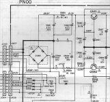
The problem was, as expected, in the power monitoring and protection circuit. Transistor 2SC3422 (QN81 on the attached schematic) failed such that the resistance (in both directions) between C & B was 1 Ohm! This compromised the 5.6V Zener (DN81) which failed short. This resulted in a near short on the 21.3V rail which in turn smoked RN81. Curiously, RN81 in my amp was a 2.2 Ohm 2W instead of the 18 Ohm 1W indicated on the schematic. It was obviously original so I replaced with the same.
All other advice was gratefully accepted and acted upon. There were loads of dry joints and two broken tracks on one of the driver boards. How it worked before the fault I will never know.
I am now organising some (silent) cooling fans in an attempt to keep this wonderful monster alive.
Thanks again.
Stuart Moore
Attachments
Schematic PM-94
Hi. A friend just gave me a gold marantz pm-94. I can't let this beautiful amp sit in my closet. The problem is, somebody replaced most internal wiring with heavy gauge monster cable. Even the power cord looks like a water hose.
The amp won't turn on. I replaced two defective output transistors and checked all connectors but no luck.
I think the internal wiring is wrong but without a scematic is not easy to check where everything goes.
If the service manual is still available please email me as it is almost imposssible to get it elsewhere. Thanks in advance.
Chris Bas
Bas_tek@hotmail.com
I've recently bought the service manual for my PM-44SE from www.manuals-in-pdf.com . I see that they sell the service manual for the PM-94 for 12.39 Euro. It took them about a week to get the message that my manual was available for download, but apart from that I had no problems with buying it. (I think the company is in Poland).
Marantz PM 94
Marantz (Japan/USA/UK) still support parts and service for the PM-94, so if you really hit the wall with DIY repair, you still can throw this at the manufacturer for repair
El Gippo
Marantz (Japan/USA/UK) still support parts and service for the PM-94, so if you really hit the wall with DIY repair, you still can throw this at the manufacturer for repair
El Gippo
I restore power to the unit now, but i can't get the speaker relay to click on.
The Big electrolytics hold power even with power off.
I measured 63V 3 hours after power off. Is this right? Testing is not safe with this voltage present. Any ideas?
The Big electrolytics hold power even with power off.
I measured 63V 3 hours after power off. Is this right? Testing is not safe with this voltage present. Any ideas?
This is normal. Discharge the capacitors by connecting a (5 to 10 ohm, 5-10watt) resistor between their poles for at least half a minute.
Measure again before proceeding. Never attempt working on the amp without discharged capacitors.
/Hugo 🙂
Measure again before proceeding. Never attempt working on the amp without discharged capacitors.
/Hugo 🙂
Hello there,
Hope you’re well?
My name is Claude I am a retired electronics engineer unfortunately had to retire because of a disability getting worse.
I have purchased a Marantz PM 94. Unfortunately when I used the amplifier no speaker relays operated. So then I soldered every joint on both power amp circuit boards. I’ve replaced all the heat sink paste and the washes on the output transistors. Then the PM94 worked okay for a couple days. Although one power amp board did get slightly hotter than the other side.
I would assume that this is a bias problem so I will be very grateful if you could send me some instructions on how to bias both of the power amplifier boards equally. Could you please send me some instructions on how to do this? This would be much appreciated.
But now there’s an even bigger problem the amplifier has gone off altogether and the Speaker relays don’t come in at all.
The front LEDs are still on. But as I said there are no Speaker relays switching in at all.
Any help with this would be very greatly appreciated.
my e-mail address is
claude2007@hotmail.co.uk
many thanks in advance.
All the very best:
Claude
Repair
Hello!
I've a problem with this amp...
In the right power channel the R767 resistor was burn out immidiately... I think it is a "protector" resistor to protect the first stage of the power amp. If I replace it with an 1/4W type, the resistor starting burn. Could You give me some advice, what can be wrong? If the resistor is taken out, the output-offset is about 7V.
I enclose the schematic.
- Status
- Not open for further replies.
- Home
- Amplifiers
- Solid State
- Marantz PM-94