D
Deleted member 543346
This amplifier has no output in right channel , so i measured voltages on stk module 3102 mk 3.
Voltages seems okey besides pin 10 , 11 and pin 5 , 6 that measures between 0 - 200mv.
Theeses voltages are inbound to stk?
Tried headphones with same result...only sound left channel.
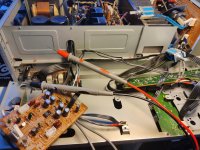
Q 715 and Q711 area seem to run varmer that the rest of the outputs.
Suppose my next step is to go upstream from q715 side and measure voltages , but i was not sure the stk module could be the reason for this.
Would be grateful for any pointers.
Here are readings from output transistors
Q 715 E 70mv , c 36v , b 655mv
Q 711 E 67mv , c 35.8v , b 650mv
Q 713 E - 103mv , c 35.8v , b 665mv
Q 717 E - 87mv , c 35,6 v , b - 665mv
Q 718 E - 265mv , c - 35,6v , b - 575mv
Q 714 E - 275mv , c - 35,7v , b - 582mv
Q 712 E - 280mv , c 35v , b - 586mv
Q 716 E - 280mv , c 35.7v b - 585mv
Voltages seems okey besides pin 10 , 11 and pin 5 , 6 that measures between 0 - 200mv.
Theeses voltages are inbound to stk?
Tried headphones with same result...only sound left channel.
Q 715 and Q711 area seem to run varmer that the rest of the outputs.
Suppose my next step is to go upstream from q715 side and measure voltages , but i was not sure the stk module could be the reason for this.
Would be grateful for any pointers.
Here are readings from output transistors
Q 715 E 70mv , c 36v , b 655mv
Q 711 E 67mv , c 35.8v , b 650mv
Q 713 E - 103mv , c 35.8v , b 665mv
Q 717 E - 87mv , c 35,6 v , b - 665mv
Q 718 E - 265mv , c - 35,6v , b - 575mv
Q 714 E - 275mv , c - 35,7v , b - 582mv
Q 712 E - 280mv , c 35v , b - 586mv
Q 716 E - 280mv , c 35.7v b - 585mv
Attachments
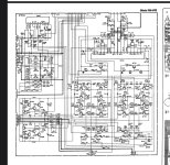
Do you have any signal at input pin 1 & 15? 5/6 & 10/11 are the outputs of the STK.
Edit: I read STK3102MKIII while the schematic says STK3062MKII but I found that the manual has both. Will look into it.
2nd. edit: Its the same pinout for both STK

Edit: I read STK3102MKIII while the schematic says STK3062MKII but I found that the manual has both. Will look into it.
2nd. edit: Its the same pinout for both STK
Last edited:

D
Deleted member 543346
Stk measurements.
10. 0v
11. 210mv
12. 55.8v
13. 55.8v
14. 0v
15. 0v
9. 56.2v
8. 0v
7. -56.5v
1. -11.8mv
2. -1.93v
3. 55.4v
4. 55.7v
5. -69mv
6. -68mv
10. 0v
11. 210mv
12. 55.8v
13. 55.8v
14. 0v
15. 0v
9. 56.2v
8. 0v
7. -56.5v
1. -11.8mv
2. -1.93v
3. 55.4v
4. 55.7v
5. -69mv
6. -68mv
Connect a signal generator or a CD player to get some signal into the amp.
I guess you haven't any AC readings on 14 & 15 either? Could you check that? I can't find where J701 is connected to, can you?
Check for AC signals on the outer contacts of J701. Carefull, the middle points contain the mains supply voltage + & - 56V

I guess you haven't any AC readings on 14 & 15 either? Could you check that? I can't find where J701 is connected to, can you?
Check for AC signals on the outer contacts of J701. Carefull, the middle points contain the mains supply voltage + & - 56V
These transistors act for the left channel wich seems OK, so I wouldn't worry about these for now.Q 715 and Q711 area seem to run warmer
These models (pm 64/84 mk1 mk2) are notorious for bad contact on the selectors, first try to tickle all the selectors vigorously after gently spraying them with contact cleaner.
Take the opportunity to inspect the solder joints.
Take the opportunity to inspect the solder joints.
What is your eperience with the STK's in that amp? I ask because most amps, not only Marantz, that came in with dead channels had a bad STK.notorious for bad contact
D
Deleted member 543346
I follow J701 to toneboard witch i have recapped and checked :
QE 01
QE 02
QE 03 and
QE 04
Will go back to check stk for ac at pin 14 and 15 as suggested.
Pots and every buttons got deoxit allready🙂
QE 01
QE 02
QE 03 and
QE 04
Will go back to check stk for ac at pin 14 and 15 as suggested.
Pots and every buttons got deoxit allready🙂
Attachments

a few have passed through my workshop and I've had a PM84 mk2 for just over ten yearsWhat is your eperience with the STK's in that amp? I ask because most amps, not only Marantz, that came in with dead channels had a bad STK.
I hope nothing went wrong when recapping? If pin 14 and 15 have no signal you'll have to trace back the signal trough the tone board until you find it on both channels. Bass, treble and balance pots are good places to check. Reminds me to ask if the balance pot is centered and not fully to the left?
Keep in mind the STK is suspect. Another approach would be to take it out and see if you got signal on the input pins on the PCB. If the STK is broken, good luck in finding one...
Keep in mind the STK is suspect. Another approach would be to take it out and see if you got signal on the input pins on the PCB. If the STK is broken, good luck in finding one...
If the STK is broken, good luck in finding [a real] one...
D
Deleted member 543346
Yes recap goes fine. Amp had a channel out before i started recapping.I hope nothing went wrong when recapping? If pin 14 and 15 have no signal you'll have to trace back the signal trough the tone board until you find it on both channels. Bass, treble and balance pots are good places to check. Reminds me to ask if the balance pot is centered and not fully to the left?
Keep in mind the STK is suspect. Another approach would be to take it out and see if you got signal on the input pins on the PCB. If the STK is broken, good luck in finding one...
Quite a few caps out of spec so far.
Stk is suspect for sure , but since all the main voltages seems ok i have hope 😅.
I know theese stk's are hard to come by nowadays.
I do some hobby refurbishing and just start to get alittle understanding of things...mutch to learn still.
Will check ac at stk now
D
Deleted member 543346
Good! Did you use a signal generator? 5mV seems little.. See if you get AC on the output pins 4/5 & 10/11.
D
Deleted member 543346
No i forgot that part 🤦
Will add signal and try again + doing measurement on pin 4/5 @ 10/11.
Now i start thinking the stk is the issue😅
Will add signal and try again + doing measurement on pin 4/5 @ 10/11.
Now i start thinking the stk is the issue😅
With AC measurements you probe for signal from a generator or CD player, radio, ..
The aim is to connect a signal source and trace that source (sine wave or music) trough a point where it vanishes.
Can be an open resitor, a broken transistor or the STK or a bad contact, a bad soldering and so on.
This can most easily be done with the meter in AC modus or a scope.
When playing music, you should be able to see the AC meter respond to the ritme of the music.
You can easily compare the left and right channels on different measuring points. Thats the nice thing about stereo gear. 🙂
As a general rule DC voltages and currents in an amplifier are there to make all active components work and to transport the music -which is always AC- through the circuit from input to output and amplify it along the way.
D
Deleted member 543346
Did a test with signal generator.
Pin 10...its clips in a way that i cannot get a stable reading.
Pin 11 starts at 5 mv and tracks with volume
Pin 14/15 starts at 5mv and tracks with volume.
Pin 4 its clips so no good reading.
Pin 5 starts at 5mv and tracks with volume.
Meaning tracks it increases when adjusting volume.
All measured in ac
- Home
- Amplifiers
- Solid State
- Marantz PM - 64 Mk 2 right channel out