Re: Re: CD63 Transistor Output Stage
Hi Champi,
Thanks for your detailed comment. I think changing that cap will make some difference. That nasty hum could be 100Hz ripple from part of the PSU seeping through. If you have a scope you should check for ripple on the PSU lines. Could be something is drawing excessive current or a cap/regulator that's badly connected. It's low frequency, so it's either that or a ground-loop.
Regards,
Ray.
pantera6 said:Just one final comment..... the CD player (after fitting the transistor stage) now has a constant hum when the preamp volume is turned all the way up (not white noise...but like 50 hz hum) and when no CDs are playing. It's definitely comming from the player... when the power's on (in stop, pause etc.) When it's playing music, I guess it's still there, but the music takes over and I don't notice it. It is otherwise not noticable, but the fact that it's still above the noise floor concerns me. I wonder if this is the noise of the DACs being amplified?? Anyone? Could this be a noisy ground or digital noise seeping through my shoddy workmanship? How can I get rid of this, or is it a known side effect of having such a great sounding passive filter + output stage? Your thoughts would be appreciated!
Champi
Hi Champi,
Thanks for your detailed comment. I think changing that cap will make some difference. That nasty hum could be 100Hz ripple from part of the PSU seeping through. If you have a scope you should check for ripple on the PSU lines. Could be something is drawing excessive current or a cap/regulator that's badly connected. It's low frequency, so it's either that or a ground-loop.
Regards,
Ray.
6h5c said:
Hi Allan,
What's your first impression of the sound?
Ray.
first impression i thought it sounded a bit veiled
left on play repeat then today same thing preferred tranny's
playing different cd's most of the day and it suddenly opened up.

must been the solen breaking in, heard it once before didn't beleive
myself about a cap untill it happened
soundstage is back nicely spaced in front of speakers.
Base is same as tranny's, i think speaker restriction
i need to find an old aldum i tested bass with. (someone going berko on a Double Bass)
more detail Glasses clinking at back of room (better positioning)
really very nice unit
will think about the 2sk117 to a 2sk170 better power handling
may change caps to 10uf's just out of interest (maybe lower inductance/impedance)
need to leave it alone and get use to the sound
in a few day's i'll try the pots
allan
Ray
the tranny version has a darlington pair output.
high gain, low output impedance.
Darlington = lower input impedance
A fet has a low input, high output impedance
wonder if this affects the low frequencies (bass)
come to think of it i think the tranny has tighter bass
but not much in it.
allan
ps prefer the fet though
Discrete out PCB
Those of you who have built the excellent output stage with the help of my PCB must have an urgent look at the connections. Brent spotted a mistake (thanks Brent) concerning the correct connection of the wires.
Where the pcb says 'LO' you have to connect 'LON' and where it says 'RO' there should be the wire coming from 'RON'.
Putting it simpler: exchange LON and LO, RON and RO.
Thanks,
Jaap
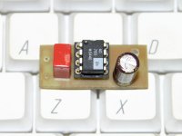
Voltage reference
I had some AD780 laying around and fitted one on a small PCB. It's a very precise voltage generator, giving out exactly 2.50Vdc.
It's a common mod for high price studio gear (analog-digital converters) to have the reference voltage modified, so I wondered why not?
For this purpose I ripped out (you know me by now) R124,R125,C123 and C124. The output connects to the hot side of R125.
Please don't ask me for results as I did several mods at once. Bottom line: the fat lady sings like never before!
Regards, Jaap
Attachments
awpagan said:i always wondered why people used expensive non polar caps in power supply apps
hmm Quirk of DIY
Now you have the break-in time for BG's
i suppose we'll hear from you in a couple of weeks😀
allan
Well, if you haven't tried it you can't know. Read about it. 😱
Regards, Jaap
awpagan said:Ray
the tranny version has a darlington pair output.
high gain, low output impedance.
Darlington = lower input impedance
A fet has a low input, high output impedance
wonder if this affects the low frequencies (bass)
come to think of it i think the tranny has tighter bass
but not much in it.
allan
ps prefer the fet though
Hi Allan,
I'm glad things opened up
 .
.You could try a mixed configuration with darlington in the output and FET's in the input stage. Maybe the tranny is a better choice as an output device. I'm curious about the effect of the pots.
Regards,
Ray.
Re: Discrete out PCB
Dat kan de beste gebeuren. Gelukkig zaten ze ALLEBEI andersom...
That can happen to the best. Lucky they were BOTH reversed...
😀
Ray.
disco said:Those of you who have built the excellent output stage with the help of my PCB must have an urgent look at the connections. Brent spotted a mistake (thanks Brent) concerning the correct connection of the wires.
Where the pcb says 'LO' you have to connect 'LON' and where it says 'RO' there should be the wire coming from 'RON'.
Putting it simpler: exchange LON and LO, RON and RO.
Thanks,
Jaap
Dat kan de beste gebeuren. Gelukkig zaten ze ALLEBEI andersom...
That can happen to the best. Lucky they were BOTH reversed...
😀
Ray.
Re: Re: Re: CD63 Transistor Output Stage
Thanks Ray/ Allan...gives me some place to start looking. Will report on the sound of the coupling cap in due course!
Cheers,
Champi
6h5c said:
Hi Champi,
Thanks for your detailed comment. I think changing that cap will make some difference. That nasty hum could be 100Hz ripple from part of the PSU seeping through. If you have a scope you should check for ripple on the PSU lines. Could be something is drawing excessive current or a cap/regulator that's badly connected. It's low frequency, so it's either that or a ground-loop.
Regards,
Ray.
Thanks Ray/ Allan...gives me some place to start looking. Will report on the sound of the coupling cap in due course!
Cheers,
Champi
6h5c said:
Hi Allan,
I'm glad things opened up
You could try a mixed configuration with darlington in the output and FET's in the input stage. Maybe the tranny is a better choice as an output device. I'm curious about the effect of the pots.
Regards,
Ray.
had thought about the bc516 in the out[ut when i was biulding it, any diff in a sim?
will try the pots in a few days. (will wait for the initial impressions to pass)
allan
Just as a simple test i'm running one channel with 2SK170 for input and output and the other channel with 2SK170 on input and a BC879 darlington (BC517 equiv) on the output.
I'll report any noticable differences later.
Brent
I'll report any noticable differences later.
Brent
It didn't take to long to decide what I prefered.
The darlington output had slightly more bass but only just.
The FET gave more air to Kralls 'the girl in the other room'.
So for me I will be sticking with a FET output.
Now to test my Black Gate caps on the output
Brent
The darlington output had slightly more bass but only just.
The FET gave more air to Kralls 'the girl in the other room'.
So for me I will be sticking with a FET output.
Now to test my Black Gate caps on the output
Brent
rowemeister said:It didn't take to long to decide what I prefered.
The darlington output had slightly more bass but only just.
The FET gave more air to Kralls 'the girl in the other room'.
So for me I will be sticking with a FET output.
Now to test my Black Gate caps on the output
Brent
with only one component changed on one channel.
the highs are not matched well between channels
stereo effect is more perceptable on highs
allan
awpagan said:
with only one component changed on one channel.
the highs are not matched well between channels
stereo effect is more perceptable on highs
allan
I had already tried the stereo test on friday. This was just another small test to compare.
I got a mate to adjust balance for this test (also the speakers were next to each other)
Both tests gave me the same answer.
Brent
rowemeister said:
I had already tried the stereo test on friday. This was just another small test to compare.
I got a mate to adjust balance for this test (also the speakers were next to each other)
Both tests gave me the same answer.
Brent
Brent
you tried a pair with all fets and a pair with fets in tranny out
if yes
sorry i got the wrong end of the stick.
Now all we need is to lower the fet out impedance to see if that brings up the bass
2sk170 2sj74 push-pull?
allan
awpagan said:
Brent
you tried a pair with all fets and a pair with fets in tranny out
if yes
sorry i got the wrong end of the stick.
Now all we need is to lower the fet out impedance to see if that brings up the bass
2sk170 2sj74 push-pull?
allan
Yes I tried all the combo's

A little more bass would be nice
Brent
rowemeister said:A little more bass would be nice
You need to DIY a really good subwoofer or two!
😀
After some google searching I found various DIY project where the 2SK170 is used in parallel to give better noise and input capacitance (equiv to the 2SK147), this has been done mainly on MC and MM applications.
I gave it a whirl and could not tell any difference . LOL. Don't know much about the MM and MC circuits but looking at them the capacitance would affect them.
Brent
I gave it a whirl and could not tell any difference . LOL. Don't know much about the MM and MC circuits but looking at them the capacitance would affect them.
Brent
rowemeister said:After some google searching I found various DIY project where the 2SK170 is used in parallel to give better noise and input capacitance (equiv to the 2SK147), this has been done mainly on MC and MM applications.
I gave it a whirl and could not tell any difference . LOL. Don't know much about the MM and MC circuits but looking at them the capacitance is a big factor.
Brent
I've been looking around for mm stuff and //2sk's
but //fets lowers input impedance, a fet is allready lower than tranny
what's why the darlington tranny
I was looking for lower output impedance
allan
- Home
- Source & Line
- Digital Source
- Marantz CD63 & CD67 mods list