Have you tried swapping the DOS inputs and/or power supplies left to right and seeing if the noise changes channel?
Good idea but not very easy to do..... I am waiting for my scope and than I will be able to search better.
Hope you've kept a wiring diagram🙂
You know its on one channel, which narrow it down...
One thing that is done when these sort of problems appear is joining ground points together with some nice thick wire, start with areas of suspicion and spread out trying different combos, sometimes the noise will go giving you a clue where the problem is (going form area to area bypassing the star ground). On quite a few commercial boards (not just audio) you will often see a nice big empty hole with a decent ground connection, just waiting for some nice hook up wire!
All flying wires carry only AC (to the 10 psu's) and DC for the 12 regs.
All GND from the psu's go back to the star.
That is why I have so much wires.
All wires are disconnectable (gold connectors) and are tagged so I can take it apart.
I am now considering building an external psu with all the TX and rectifying boards.
It will take some time.... will report latter.
Now the output cap bypass I just did restored the marvellous spatiality I am used to in my other builds so at least I am enjoying it now 🙂
Bit OT, but at the last clear-out of our attic it looks like my CD63, that I was saving for some future fun (the laser had gone!) has been binned by an over enthusiastic missis.
Good look with the fault finding🙂
Good look with the fault finding🙂
Aghhhhhh! I broke it!
Well, to be exact, it broke itsself. But at the end of a lovely evening's listening, my player is dead 🙁
I've got no display on the front whatsoever and the disc just spins faster and faster until I turn the whole thing off. It spins regardless of whether there's a disc in there or not. I've checked a few voltages and can't see an obvious issue.
Any pointers gratefully received....
I'd start by checking all the voltages you easily can while the player is still together, e.g. regulator in/out, CPU 5v supply, etc.
I also tend to gently press the top of the PCB while it's on to see if it affects the spinning of the disc at all. That's revealed the approximate location of a cracked trace several times.
After that, take the board out and check for continuity. It's been a while since I debugged something like this, but it might be your DAC clock...
Good luck. I'm sure you'll find it.
Thanks Ben. Pretty sure I had wildly spinning disc, but with display working when I had clock issues before. I've done a quick search and can see Rcruz had a similar issue where he'd lost power to the µCon. I'll give that a check tomorrow.
I encountered once a dead screen and the problem was found due to the defective voltage regulator. Change the voltage regulator and the screen came back normal. Check the voltage output of the regulators as a first step.
I've had a very quick check on my way out this morning and I'm getting 4.85v at pin 1 of the µCon which seems a little low to me. It's got it's own dedicated 7805 regulator so I can check/replace that easily. I wonder if the µCon chip's dead though...
For reference, here's what my player looks like these days
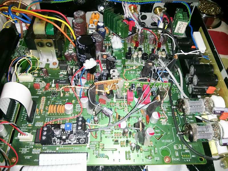
For reference, here's what my player looks like these days
I've had a very quick check on my way out this morning and I'm getting 4.85v at pin 1 of the µCon which seems a little low to me. It's got it's own dedicated 7805 regulator so I can check/replace that easily. I wonder if the µCon chip's dead though...
For reference, here's what my player looks like these days
I would have thought 4.85 was well within the working range.
The very fast spinning seems to have stopped. Now it's accelerating the disc quite slowly and only spinning it what seems to be a fairly normal speed.Speed spinning might be due to a faulty driver chip... had to replace one once 🙁
Yes, I don't think that chip is that fussy, I just noted it because I wondered whether the chip was damaged and dragging the voltage down as it's right next to its own dedicated 7805 regulator and I would expect it to be bang on 5v. I need to pull that reg off and see if it gives 5v when not connected to the u-com I guess.I would have thought 4.85 was well within the working range.
I really need another unmolested cd63 sat next to it so I can compare voltages in and out of the servo driver and u-com chips I guess.
I'll try and double check more voltages this eve. Any pointers gratefully received 🙂
Whenever I've had similar uncontrollable/continuous spinning it's been related to not finding and locking to the clock. If you have a seperate supply to the clock make sure it's working correctly and powering up at the same time as the rest of the player, if you've got a big cap in there it could be delaying the clock start.
Pete
Pete
thanks, yes. I had very similar disc spinning issues while I was fitting the clock initially (Ray's Flea with Tentlabs XO) and had the decoder clock signal disconnected.Whenever I've had similar uncontrollable/continuous spinning it's been related to not finding and locking to the clock. If you have a seperate supply to the clock make sure it's working correctly and powering up at the same time as the rest of the player, if you've got a big cap in there it could be delaying the clock start.
Pete
I checked again tonight and found that the front display seems to work after a good few seconds of being blank, just displaying 'disc'. Not sure if I missed this before..
I checked the Flea and it correctly has 5v going to the XO. I also checked for clock signal going to the DAC, decoder and servo just using my multimeter on the DC setting and I can see around 1.5v if I measure at the point where the new clock signal wire joins to the top of the board. Can't say for certain if the clock signal is correct, but I would assume that I wouldn't see the voltages there if it wasn't working as expected.
I also checked my 6 x 7809/7909 regulators for the servo chips and can see +9v and -9v for those as expected.
thanks, yes. I had very similar disc spinning issues while I was fitting the clock initially (Ray's Flea with Tentlabs XO) and had the decoder clock signal disconnected.
I checked again tonight and found that the front display seems to work after a good few seconds of being blank, just displaying 'disc'. Not sure if I missed this before..
I checked the Flea and it correctly has 5v going to the XO. I also checked for clock signal going to the DAC, decoder and servo just using my multimeter on the DC setting and I can see around 1.5v if I measure at the point where the new clock signal wire joins to the top of the board. Can't say for certain if the clock signal is correct, but I would assume that I wouldn't see the voltages there if it wasn't working as expected.
I also checked my 6 x 7809/7909 regulators for the servo chips and can see +9v and -9v for those as expected.
Even if the clock signal is correct, if it's starting up slowly (in relation to the dac chip?) it doesn't get locked to. Given your display seems to be powering up slowly it might be worth investigating this further. You could try warming up the player and then turning off/on quickly.
Pete
Thought I'd share what I have done to avoid all that spaghetti shown in some previous posts!
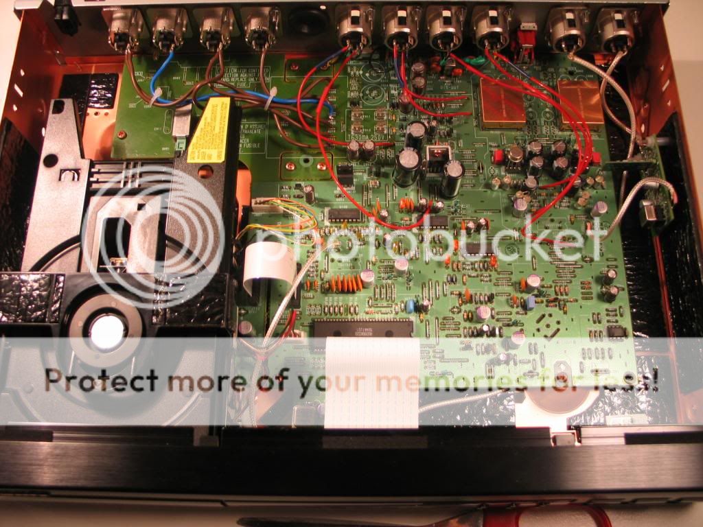
This is my player with the main tx removed to another box. The brown and blue wires at top left are the AC feeds from the main tx which are attached to their respective original power rails. The red wires are separate feeds from separate trannies for the servo, the output stage and DAC analogue and DAC digital. The silver wires are the clock feeds (servo and DAC). All connections are XLRs. My mentor/guru reddish, an occasional poster on here, has been of tremendous help to me.
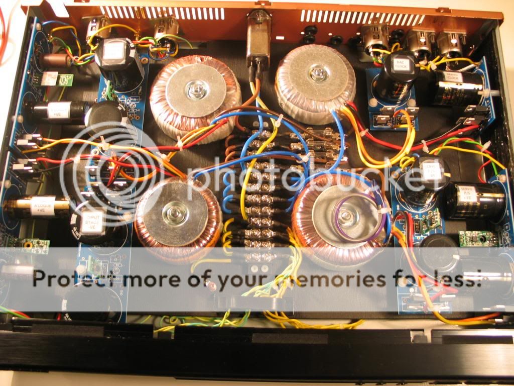
This is my second player with guts removed and a false floor constructed. This carries txs powering the 2 clocks (top right), the servo (bottom right), the output stage (top left) and the 2 analogue DAC rails (bottom left). All the AC is in this box, with only DC feeds into the main player (all the red and silver wires).
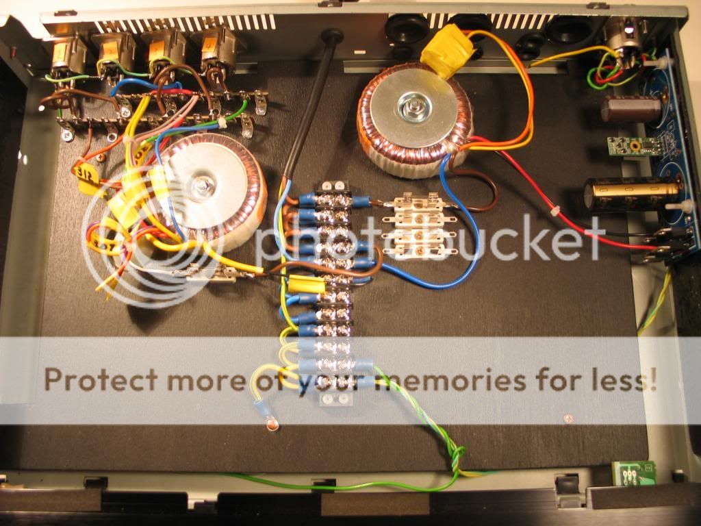
This is my third player with guts removed and a false floor constructed. This carries the re-located main tx (on left) and a tx (on right) feeding the digital DAC rail. I have yet to fit a filtered IEC socket to this box as I have done with the other box. Eventually the 2 'transformer' boxes will each have an on/off switch. The diode indicating 'on' will be neatly fitted into the headphone socket. Note: more room for more trannies in this box! Note also the star earthing.
This is my player with the main tx removed to another box. The brown and blue wires at top left are the AC feeds from the main tx which are attached to their respective original power rails. The red wires are separate feeds from separate trannies for the servo, the output stage and DAC analogue and DAC digital. The silver wires are the clock feeds (servo and DAC). All connections are XLRs. My mentor/guru reddish, an occasional poster on here, has been of tremendous help to me.
An externally hosted image should be here but it was not working when we last tested it.
This is my second player with guts removed and a false floor constructed. This carries txs powering the 2 clocks (top right), the servo (bottom right), the output stage (top left) and the 2 analogue DAC rails (bottom left). All the AC is in this box, with only DC feeds into the main player (all the red and silver wires).
An externally hosted image should be here but it was not working when we last tested it.
This is my third player with guts removed and a false floor constructed. This carries the re-located main tx (on left) and a tx (on right) feeding the digital DAC rail. I have yet to fit a filtered IEC socket to this box as I have done with the other box. Eventually the 2 'transformer' boxes will each have an on/off switch. The diode indicating 'on' will be neatly fitted into the headphone socket. Note: more room for more trannies in this box! Note also the star earthing.
An externally hosted image should be here but it was not working when we last tested it.
Hi,
I was modifiying my CD67. I tried to change the transport. After changing I am getting Radial Error ( ERR 10 ). I removed and re inserted the ribbon cable and it started working for some time. After an hour it again stopped reading disc. Disc is not spinning when loaded. In display, "Disc" is blinking for 2 or 3 times and no change. What could be the mistake?
Thanks
Badri
Attachments

Thought I'd share what I have done to avoid all that spaghetti shown in some previous posts!
This is my player with the main tx removed to another box....
As Eddie Booth would say if he saw your player...blood-y NORA!
(classic Brit comedy there for you, Lymmlad)
Huge effort there!
As Eddie Booth would say if he saw your player...blood-y NORA!
(classic Brit comedy there for you, Lymmlad)
Huge effort there!
Thanks, Stuey. So far it has been a labour of love... with some frustrations thrown in for good measure.
Forgot to mention that I have also cut a hole in the floor of the main box to get at the innards. I used a Dremel for this with a small circular cutting wheel.


Hi,
I was modifiying my CD67. I tried to change the transport. After changing I am getting Radial Error ( ERR 10 ). I removed and re inserted the ribbon cable and it started working for some time. After an hour it again stopped reading disc. Disc is not spinning when loaded. In display, "Disc" is blinking for 2 or 3 times and no change. What could be the mistake?
Thanks
Badri
Reason identified. It looks like laser is a faulty one. Thanks
- Home
- Source & Line
- Digital Source
- Marantz CD63 & CD67 mods list