Hi Ray
A very Great site. Before your last post, while checking your profile I have already visited your great site. Many photos.
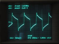
I must let you know a little secret: I removed the Spdif output transformer and replaced it with 300 and 75 ohm voltage divider and that caused the non reading of CDs and hence having to adjust the laser trimmer. But the output wave looked much better (will post photo later)
I wonder how they are related
Thanks and regards
A very Great site. Before your last post, while checking your profile I have already visited your great site. Many photos.
I must let you know a little secret: I removed the Spdif output transformer and replaced it with 300 and 75 ohm voltage divider and that caused the non reading of CDs and hence having to adjust the laser trimmer. But the output wave looked much better (will post photo later)
I wonder how they are related
Thanks and regards
Thanks, glad you like my site 😀
The decoder is probably having a hard time to drive the 375 ohm it sees at it's output. The reason the waveform is distorted is because the transformer is (probably) crap, and/or not properly terminated. Did you measure with 75 ohm termination at the side of the scope?
Ray
The decoder is probably having a hard time to drive the 375 ohm it sees at it's output. The reason the waveform is distorted is because the transformer is (probably) crap, and/or not properly terminated. Did you measure with 75 ohm termination at the side of the scope?
Ray

So you got better waveform transfer without the TX....
What are your subjective impressions regarding the output sound ?
Can you post your listening impressions ?
Regards
Ricardo
What are your subjective impressions regarding the output sound ?
Can you post your listening impressions ?
Regards
Ricardo
So you got better waveform transfer without the TX....
No, you don't understand...
The change in shape can be caused by an incorrect measuring method, and not by removing the transformer. The first picture looks like a bad overshoot caused by an unadjusted scope probe. If you do not terminate the output properly, and use an unadjusted probe, you can't say anything about the signal.
Ray
Thank you Ray
Now I get the idea... To improve this area, we should replace the TX by a better one or is there any better alternative ?
Ricardo
Now I get the idea... To improve this area, we should replace the TX by a better one or is there any better alternative ?
Ricardo
Ok 😀
Yes, the TX can be replaced by something better, but first you have to find out what the turns ratio is. Is it 1:1 or 1:2 or 2:1... Then you can pick a high frequency tranny from Pulse or Murata etc. and replace it. In the end, the output impedance has to be 75 ohm. While you are at it, change the plastic cinch socket for a decent 75 ohm BNC connector, and use a proper 75 ohm coax cable between player and DAC.
At the DAC side, the S/P-dif input should have a BNC connector as well, and the input has to be terminated with 75 ohm. The DAC can also have a crappy input transformer, so it should be replaced too. Only if the whole chain is optimized, you'll get a proper S/P-dif signal 😀.
I'll see if I can do some measurements today, to get the turns ratio.
Regards,
Ray
Hi Ray
Thank you.
I have increased the resistance of the voltage divider to 910 ohm and 300 ohm. Most discs can be read except a few
I look forward to your measurment and hopefully able to find a trans that fits
regards
Audiohifi
Thank you.
I have increased the resistance of the voltage divider to 910 ohm and 300 ohm. Most discs can be read except a few
I look forward to your measurment and hopefully able to find a trans that fits
regards
Audiohifi
Ok 😀
Yes, the TX can be replaced by something better, but first you have to find out what the turns ratio is. Is it 1:1 or 1:2 or 2:1... Then you can pick a high frequency tranny from Pulse or Murata etc. and replace it. In the end, the output impedance has to be 75 ohm. While you are at it, change the plastic cinch socket for a decent 75 ohm BNC connector, and use a proper 75 ohm coax cable between player and DAC.
At the DAC side, the S/P-dif input should have a BNC connector as well, and the input has to be terminated with 75 ohm. The DAC can also have a crappy input transformer, so it should be replaced too. Only if the whole chain is optimized, you'll get a proper S/P-dif signal 😀.
I'll see if I can do some measurements today, to get the turns ratio.
Regards,
Ray
I looked into this last year and after some investigation of the manual and googling came to the conclusion that a MURATA 76601/3C (TRANSFORMER, PULSE, 1:1; Inductance:219µH; DC Resistance:0.5ohm; ET Constant:5.5V/µs; Isolation voltage:500V rms; Winding Configuration:1:1; Turns Ratio:1:1😉 was what was needed for my CD67.
Never got round to fitting it yet though so can't defo say that it worked/made any difference.
Regards
Pete
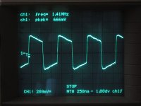
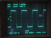
This second pic is the same output, only now terminated with a 75 ohm resistor.
For a standard transformer, I'd say it doesn't even look that bad!
For a standard transformer, I'd say it doesn't even look that bad!
Attachments
Last edited:
EERA :: Lecteur CD HIFI Haute fidélité - Marseille Go to "Temptation" and click on right upper "documentation" PDF. Scroll down to the image. My question is about the damping of the little spinning disk in the center of the disk sled. They have put te same damping material as is used for the case work. I have tried this but it's very hard to cut an exact circle in this stuff. I also wonder about adding weight to this piece or what happens when it's not exactly round and centered. Any one tried this and found any improvements?
I think this has been covered earlier on this site. 1 euro and other various coins were used I believe. As far as I remeber it was used to good effect on earlier versions of the sled but later versions were redesigned so it wasn't needed.
Regards
pete
Regards
pete
This second pic is the same output, only now terminated with a 75 ohm resistor.
Wrong termination. Crappy transformer.
76601/3C is only marginally better, a nightmare to cancel leakage inductance. Forget about it.
For a standard transformer, I'd say it doesn't even look that bad!
Are you joking? 😕
I missed it...too many pages to cover. Mine's an old sled I would imagine. Ray? Brent?I think this has been covered earlier on this site. 1 euro and other various coins were used I believe. As far as I remeber it was used to good effect on earlier versions of the sled but later versions were redesigned so it wasn't needed.
Regards
pete
Hi shepperd
Some of us used a small coin covering the magnetic center of the mech.
In my case I could not use it because my magnetic center actually works off center.
Please let us know if yours looks steady when spinning.
Regards
Ricardo
Some of us used a small coin covering the magnetic center of the mech.
In my case I could not use it because my magnetic center actually works off center.
Please let us know if yours looks steady when spinning.
Regards
Ricardo
- Home
- Source & Line
- Digital Source
- Marantz CD63 & CD67 mods list