Look at the back ground of the sell, seems the fight is on 😉
Wich one of you is the CD Mod Guru? 😀
Wich one of you is the CD Mod Guru? 😀

I cannot understand why someone would feel so threatened by a nooble_cd_mod_guru_meister
Lee.
Lee.
LOL
I used his image (like everyone else does on ebay) to sell one of his products and he complained like a baby. So I relisted and took a piccy that is very similar to the one he uses lol.
It did annoy me a little.
Brent
I used his image (like everyone else does on ebay) to sell one of his products and he complained like a baby. So I relisted and took a piccy that is very similar to the one he uses lol.
It did annoy me a little.
Brent


From the SAA7345 datasheet:
The motor servo has the operation modes as shown in Table 9 and is controlled by the motor mode register
(address 0001).
MODE DESCRIPTION
Start mode 1 Disc is accelerated by applying a positive voltage to the spindle motor. No decisions are involved and the PLL is reset. No disc speed information is available for the microcontroller.
Start mode 2 The disc is accelerated as in Start mode 1, however the PLL will monitor the disc speed. When the disc reaches 75% of its nominal speed, the controller will switch to Jump mode. The motor status signals are valid (register 0010).
Jump mode Motor servo enabled but FIFO kept reset at 50%. The audio is muted but it is possible to read the subcode.
Jump mode 1 Similar to Jump mode but motor integrator is kept at zero. Used for long jumps.
Play mode FIFO released after resetting to 50%. Audio mute released.
Stop mode 1 Disc is braked by applying a negative voltage to the motor. No decisions are involved.
Stop mode 2 The disc is braked as in Stop mode 1, but the PLL will monitor the disc speed. As soon as the disc reaches 12% of its nominal speed, the MOTSTOP status signal will go HIGH and switch the motor servo to off mode.
Off mode Motor not steered.
---
My decoder seems to be in Start mode 1 permanently, as it just goes and goes at max. speed. Could this be caused by absence of PLL signal, in turn caused by absense of proper signal HFREF and HFIN (pins 8 and 9) ?
Steve,
Usually when a CD63/7 fails it's because a voltage rail has been knocked off, something has been shorted out or one of the two ribbon connectors has failed.
If none of your chips have been fried then check all their voltages, not just the one you've just done. Check your clock is connected ok and has the correct voltage (if used).
If these things are ok and visually everything looks spot on and there are no bad smells then fiddle with the ribbon connectors, carefully.
Have you regulated the servo drivers? This can stop it from working or make it intermittent.
Simon
Simon,
Thanks. I hope the Decoder wasnt fried... did smell anything and visually looks ok... I suspect though that the SAA7345 is sending out a command to the servo amps/motor to start running. Not sure if that would be a response that could be sent out from a fried chip (probably it would not send out anything at all).
TDA1301 is regulated, but I tested it prior to regulating the decoder, and then it worked. It stopped working when I regulated the decoder.
Clock setup is still stock. I'll check the voltages of the chips, need to buy a scope to find out more I think...
Installed servo regulator yesterday. Very nice, indeed.
Couldn't solder to the jumper, so I had to run wires, grounds too, from the bottom of the board. The first two 7805's I tried failed miserably. First I though I didn't need to scrape the lacquer of the top of the pcb, I'll just solder it to the ground of the resistor I just took out😱. Did it for both feeds. After I woke up, I solder bridged two pins🙁. Then I cut those two out and installed two new ones correctly. Also, ddn't pay attention when reconnecting the ribbon cable to the front panel, and crimped a couple pins on it🙁. Now the display does not work, which is very annoying. Definitely have to fix that.
On to the DAC.
What a great feeling to fix something... my machine runs again. Turned out to be that I broke a soldering pad, so the Digital Vin on the decoder had 0. Strange response of the chip to just let the motor spin at max speed.
When it aint broke, break it. Then fix it!
When it aint broke, break it. Then fix it!
..................
When it aint broke, break it. Then fix it!
Where have I heard that before ??????
For expert advice on how to break pads. contact Simonty
Andy
Glad you sorted it Steve, it's usually something we do ourselves, as I know only too well.
Yes, I was good at breaking pads but those days are behind me, it's all clean work now Andy 🙂
I will post a picture of my current cd63 project in a bit.
Yes, I was good at breaking pads but those days are behind me, it's all clean work now Andy 🙂
I will post a picture of my current cd63 project in a bit.
CD67 servo amplifiers
Hy,
interesting comments.
has anyone tried to increase regulated 5V for the three servo amplifiers in a CD67 ?
According to datasheet TDA7073 up to 18V should be the maximum.
I'm modding a CD63 at the moment. ...
I just regulated voltages to two the three servo amplifiers using 7808 / 7908. The results are amazing! The detail, openness, space, smoothness and bass control have really improved a lot! The player sounds very funky.
Simon
Interesting comments Glenn. I feel it's worth pointing out that when compared with like-for-like mods many people prefer the CD67. The CD67 has a regulated 5V for the servo amps / driver op-amps. I'd still recommend people buy a CD63 though, ...
Simon
Hy,
interesting comments.
has anyone tried to increase regulated 5V for the three servo amplifiers in a CD67 ?
According to datasheet TDA7073 up to 18V should be the maximum.
She's not bad, she's just drawn that way...
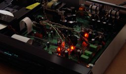
Hi there,
here is my xmas tree!
I had to use only red Leds to get it right...
The CD-43 is finished, it will have to face the CD-40 wich comes next week =)
I'll do sound report of the CD-43 after a decent burn-in, RC LPF and ringing avoided 317 may help a lot.
Another thank you to you all for helping, the result is at least better than the factory player 😉
A grateful Matthieu,
merry melodies to you all!
Attachments
Yep,
and I can check if at least 2 regs are working through the removed headphones' jack 🙂
But it does not sounds good. It's held back, lack energy and dynamic. Maybe I need to bypass caps (I did not at all, only big lytics and bypass at pins) or such to improve response? Like very input legs of the regs? That annoying bypass caps story...
Or my output caps combo are not that great, or the BG at DAC's analog and DOS (and pre-amp also!) take years to burn-in... albeit the xmas tree and moved furnitures changed sound and what I am used to... I don't like the way it sounds now 🙁
Matthieu
- Home
- Source & Line
- Digital Source
- Marantz CD63 & CD67 mods list