SimonY,
We don't sell TENT Labs stuff at all, we just use TENT Labs oscillators in our Upgrades and in our TerraFirma Clocks. What other things they make I have really no knowledge, and have never tried, although I am about to try out their tube negative bias module.
Regards, Allen
www.vacuumstate.com
We don't sell TENT Labs stuff at all, we just use TENT Labs oscillators in our Upgrades and in our TerraFirma Clocks. What other things they make I have really no knowledge, and have never tried, although I am about to try out their tube negative bias module.
Regards, Allen
www.vacuumstate.com
Thanks Allen. Truth is I was being a bit naughty and pulling your leg. Have you ever considered selling low voltage regs?
Simon
Simon
We developed low voltage current sourced shunt regs and actually posted them on our website to see what the reaction would be prior to actually getting any quantity built up. And in a year, one enquiry...
In contrast we sell well over 100 of our high voltage (for tube circuits) CCS'd shunts regs per year, so we just gave up on the lo voltage ones.
If there was interest, we could put them into production almost immediately.
Regards, Allen
www.vacuumstate.com
In contrast we sell well over 100 of our high voltage (for tube circuits) CCS'd shunts regs per year, so we just gave up on the lo voltage ones.
If there was interest, we could put them into production almost immediately.
Regards, Allen
www.vacuumstate.com
Allen,
I guess the clue's in your company's name! Valves = high voltage and record players. At least that's the stereotype. Nobody would be thinking to look for those kind of regs.
Simon
I guess the clue's in your company's name! Valves = high voltage and record players. At least that's the stereotype. Nobody would be thinking to look for those kind of regs.
Simon
Allen Wright said:Ray,
Cool.
I have sent you a private email via the forum.
I could find no way of emailing you from your website. When I tried the "Contact Ray" button, it just went to a page on this forum... That can't do much for business?
Regards, Allen
www.vacuumstate.com
That's ok, I don't own a business and it prevents a lot of spam. Only people who are REALLY interested will go on and register to this forum 🙂
Ray
Malefoda said:Guys,
you're trying to compare modded players, well, may I ask how much money is needed to make them all real opponents to each others?
Maybe I can give a few examples to help put things in perspective 😀.
I bought my SA8400 player as an occasion for €450,-. The costs of the parts for the mods are at least that same amount, but probably higher. Should I have bought a €1000,- player instead? I think not, because this one sounds way much better.
Last player I did was a CD63mkII. The player cost me €65,- including a new VAM unit. I sold it for about €250,- with the 'basic' mods: upgrade PSU, caps, filter, damping, no extra PSU's and a simple CD clock. And it won't make me rich...
Point is, the amount of money for mods is a multiple of the commercial value of the player. Not to mention the amount of time you have to invest. But what you get in return is something much more valuable: your OWN DIY player 😀. The money is absolutely worth it in my opinion!
Regards,
Ray
I totally agree with Ray.
I've tried doing a few basic mods to 63's to fund my obsession with modding! It doesn't work. People are scared of players that have been tweeked by enthusiasts (some of which know as much, if not more than some professionals).
As for the mods, as you say, a £450 player + £450 mods is likely to beat a £2k player!
I home demo'd a MF A5.5 (original retail price was £2k) It was reasonable but its not in the same league as a well modded 63 and a mile away from my TDA1541 player!
Well modded players are in a totally different class.
Also, Musical Fidelity now offer a blueprinting service for their kit.
http://www.musicalfidelity.com/tune/index.html
Mods for PSU, clock etc (no low noise regs!!!). For a few hundred £ you can have £50-60 worth of mods mentioned in these forums. It seems even the manufacturers now are accepting the fact that what we do here is positive.
Edit- you can see the details of the mods offered by selecting a product from the left on the link above. It has to be said they are not very advanced mods!!! Pretty gold sockets, op amps and lots of checking but not much upgrading!
UV101 said:Pretty gold sockets
I prefer thick silver plate! Not heard of this "blueprinting" service before, I think it's a fun idea 😎
Simon
I am happy with my mod so far. This inc the blackgate on pwr supply and the NX on the opamp, clock, opamp, silver wire, etc. However, I wonder what is the effect if separate power supply such as teddyreg, or other shunt reg for the opamp. what sort of improvement putting the shunt reg which is powered by separate tranny and diodes?
6h5c said:
Hi Allen,
They are indeed Tentlabs shunts and the pinout is equal to the 78xx/79xx regulators. The current is set by a few resistors, one for the total CCS current and two for the output voltage, that is held at the desired voltage by shunting part of the current to GND through a resistor.
They are set by Tentlabs, but I modified some of them to lower the dissipation, because the load current was quite small. I generally make the shunt current as large as the max. load current, so 'incoming' CCS current is 2x Iload.
Ray
Hi Ray,
I'm about to redo my DOS and add the Tentlabs shunts. But, Guido makes a 15V shunt and the DOS shows 12V, so what do I do to the +- 15V shunt to get the need +- 12v?
Steve
Originally posted by stvnharr
Hi Ray,
I'm about to redo my DOS and add the Tentlabs shunts. But, Guido makes a 15V shunt and the DOS shows 12V, so what do I do to the +- 15V shunt to get the need +- 12v?
Steve
You can adjust the output voltage by changing one or two SMD resistors on the PCB (the output voltage divider basically). I don't have the values for 12V here at the moment, but when I get home this afternoon I can look them up for you.
If the input voltage is high and the load current is low, the shunts can get pretty warm; in that case you can adjust the current as well by changing a resistor in the CCS, or use an extra resistor that can be mounted on the back of the shunt.
Ray
ccschua said:I am happy with my mod so far. This inc the blackgate on pwr supply and the NX on the opamp, clock, opamp, silver wire, etc. However, I wonder what is the effect if separate power supply such as teddyreg, or other shunt reg for the opamp. what sort of improvement putting the shunt reg which is powered by separate tranny and diodes?
As it's an op-amp the gains will be modest. Value-for-money is not high compared to feeding the DAC, decoder and/or servo rails with low-noise regs and dedicated supplies. It depends if you're happy with it just sounding "a bit nicer" or would prefer loads more detail and clarity.
Simon
Originally posted by SimontY
As it's an op-amp the gains will be modest. Value-for-money is not high compared to feeding the DAC, decoder and/or servo rails with low-noise regs and dedicated supplies. It depends if you're happy with it just sounding "a bit nicer" or would prefer loads more detail and clarity.
Simon
Then you would have to do all those steps. IMO, every step makes it sound a bit nicer, together they create the end result. An opamp certainly benefits from a less noisy supply!
Ray
True! But better players, like the CD17KI, sound almost acceptable in stock form. They need fewer upgrades to achieve greatness.
For me the stock cd17KI sounds better than brand new players such as the Naim cd5i. Ok they are cheaper than the 17 was but after 10 years you would expect more.
Brent
Brent
Can some one point me to the schematic with the shunt reg supplying the dac and outputstage.
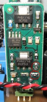
Here's a picture of a 12V shunt I modified. This is the negative version by the way.
Originally, a 15V shunt has one 2k2 SMD resistor marked '2201' or '222' in place in the lower red circle. To make the shunt 12V, you have to replace it by a 1k6 resistor.
The PCB has an empty space for an extra resistor (in the upper circle) that is in parallel with the first 2k2 or 1k6, so you can compose the desired value of two resistors (as I did, by using a 2k0 and 8k2 in parallel because I didn't have the 1k6 at hand).
Regards,
Ray
Attachments
- Home
- Source & Line
- Digital Source
- Marantz CD63 & CD67 mods list