SimontY said:Are you going to the UK DIY Audio meet in Chesterfield next month? I will take my CD63 to show there.
Chesterfield? Is that north of Watford?
Glenn2 said:
Chesterfield? Is that north of Watford?
Ahh, the London stereotype. Very good!
rowemeister said:Hi
7 regs
3 for DAC
2 for decoder
2 for servo.
Brent
and 7 PSU's ?
regards
aquar
Hi all,
Last night I replaced T4 (BC517) in the discrete output stage with 2SK170 BL (from HDAM), first impression bass more dept but litlle bloated (maybe need more time for break in) or .......??
Basicly, 2SK170 BL better than BC517.
regards
aquar
Last night I replaced T4 (BC517) in the discrete output stage with 2SK170 BL (from HDAM), first impression bass more dept but litlle bloated (maybe need more time for break in) or .......??
Basicly, 2SK170 BL better than BC517.
regards
aquar
67se opamp bypass caps question
hello! i have replaced the original 2124 opamps in this unit using ad8610s for ic605, and a ad8620 for ic606 that i had on hand. i've put .1mf stacked film panasonic caps across the +/- power pins on bottom of board and added an extra nichicon 1k mf to each, +/- power rail as close to opamps as possible for extra decoupling. also using lm317/lm337 for the 12 volt regulators. should i also, add +/- power pin bypassing on opamps with small .01 or .1mf caps to ground plane? i have on hand right now .01mf orange drops and some .1mf stacked film panasonic caps orange drops are the 615 axial and the stacked films are the radial package. i was also wondering what an average price for four 16v. 470mf caps to replace the 4 red caps around the opamps which would be nothing real expensive just a step up from what's there now as i am on a fixed income. Thanks, and a great forum just wish i could have got started years ago in diy upgrades. 🙂
hello! i have replaced the original 2124 opamps in this unit using ad8610s for ic605, and a ad8620 for ic606 that i had on hand. i've put .1mf stacked film panasonic caps across the +/- power pins on bottom of board and added an extra nichicon 1k mf to each, +/- power rail as close to opamps as possible for extra decoupling. also using lm317/lm337 for the 12 volt regulators. should i also, add +/- power pin bypassing on opamps with small .01 or .1mf caps to ground plane? i have on hand right now .01mf orange drops and some .1mf stacked film panasonic caps orange drops are the 615 axial and the stacked films are the radial package. i was also wondering what an average price for four 16v. 470mf caps to replace the 4 red caps around the opamps which would be nothing real expensive just a step up from what's there now as i am on a fixed income. Thanks, and a great forum just wish i could have got started years ago in diy upgrades. 🙂
Hi,
I wouldn't bother changing the red caps. It might make it sound worse, as they're nice caps!
Simon
I wouldn't bother changing the red caps. It might make it sound worse, as they're nice caps!
Simon
thanks, i'll keep them then but do you think i should put the small bypass caps? or maybe wait till i can get some smd caps? Thanks! 🙂
crippledchicken said:thanks, i'll keep them then but do you think i should put the small bypass caps? or maybe wait till i can get some smd caps? Thanks! 🙂
It depends if you want it to be "accurate" sounding but less musical or just nice and pleasant. If the latter you won't want to use any bypass caps across other caps. Those red ones are Elna Cerafine, widely regarded as some of the best "sounding" caps. If you can find some, say 220uF, Elna Cerafine or Elna Silmic it would be worth replacing them. They are gonna be old.
Re: 67se opamp bypass caps question
Hi cripp,
Ofcourse, this is great forum,great topics and great people.
You will find improvement of sound quality every step you tweaked.
After a few hour running with 2sk170 , bass more detail and deep, soundstage more natural, discrete output filter made soundstage 'rectangular/square effect'...... I can feel/see sound come from back corner behind the speaker, with opamp the soundstage like as oval/round shape.....I can not feel/see sound come from back corner behind the speaker..... sorry difficult to speak in english, basicly with discrete I got big improvement ,bigest improvement sound quality I have done.
regards
aquar
crippledchicken said:hello! i have replaced the original 2124 opamps in this unit using ad8610s for ic605, and a ad8620 for ic606 that i had on hand. i've put .1mf stacked film panasonic caps across the +/- power pins on bottom of board and added an extra nichicon 1k mf to each, +/- power rail as close to opamps as possible for extra decoupling. also using lm317/lm337 for the 12 volt regulators. should i also, add +/- power pin bypassing on opamps with small .01 or .1mf caps to ground plane? i have on hand right now .01mf orange drops and some .1mf stacked film panasonic caps orange drops are the 615 axial and the stacked films are the radial package. i was also wondering what an average price for four 16v. 470mf caps to replace the 4 red caps around the opamps which would be nothing real expensive just a step up from what's there now as i am on a fixed income. Thanks, and a great forum just wish i could have got started years ago in diy upgrades. 🙂
Hi cripp,
Ofcourse, this is great forum,great topics and great people.
You will find improvement of sound quality every step you tweaked.
After a few hour running with 2sk170 , bass more detail and deep, soundstage more natural, discrete output filter made soundstage 'rectangular/square effect'...... I can feel/see sound come from back corner behind the speaker, with opamp the soundstage like as oval/round shape.....I can not feel/see sound come from back corner behind the speaker..... sorry difficult to speak in english, basicly with discrete I got big improvement ,bigest improvement sound quality I have done.
regards
aquar
hello, and english is fine! that's sounds like a very interesting mod i will have to read up on it! Thanks very much 🙂
Help needed...
Hi chaps,
I have a problem...
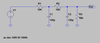
I've just changed the passive filter between the DAC and the Zapfilter I'm using. I wanted to get rid of the slight treble rolloff and improve rejection of the ultrasonic stuff.
It sounds nice and it's opened out the treble but I now have mains hum breaking through. Is it anything to do with the inductors? I haven't changed much!
This is what the circuit WAS:
Hi chaps,
I have a problem...
I've just changed the passive filter between the DAC and the Zapfilter I'm using. I wanted to get rid of the slight treble rolloff and improve rejection of the ultrasonic stuff.
It sounds nice and it's opened out the treble but I now have mains hum breaking through. Is it anything to do with the inductors? I haven't changed much!
This is what the circuit WAS:
Attachments
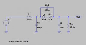
...and this is what it is now... note that the cap and resistor on the inductor are just the series resistance and parallel capacitance (calculated from the self-resonant freq) of the inductors... and the odd value of resistors is just becuase they are Welwyns.
Baffled.... 😕
Baffled.... 😕
Attachments
I think your guess is right, and it is the inductor. The impedances either side of the inductor are quite high at LF - 2.5K minimum - that's probably enough to turn a tiny induced current into a significant voltage.
Easy to test - just tack a wire short across L1. If the hum goes away...
Easy to test - just tack a wire short across L1. If the hum goes away...
martin clark said:I think your guess is right, and it is the inductor. The impedances either side of the inductor are quite high at LF - 2.5K minimum - that's probably enough to turn a tiny induced current into a significant voltage.
Easy to test - just tack a wire short across L1. If the hum goes away...
Cheers Martin. Do you think putting them on the underside of the PCB would help? Lying horizontally. Would the bottom of the chassis and the PCB (with ground plane) shield them from either side, and would the fact they are then horizontal change things in relation to the magnetic field which I suppose is coming from the transformers?
The hum source is definitely inside the player.
Hi,
does anybody have the service manual in pdf of the 63 ?
I would like upgrade mine following your instructions, but the service manual is a good fallback, just in case ...
thanks,
laurent
does anybody have the service manual in pdf of the 63 ?
I would like upgrade mine following your instructions, but the service manual is a good fallback, just in case ...
thanks,
laurent
aquascop said:Hi,
does anybody have the service manual in pdf of the 63 ?
I would like upgrade mine following your instructions, but the service manual is a good fallback, just in case ...
thanks,
laurent
Check out Ray's page here. He's the man who started this monster thread!
Glenn - if it is pick-up due to highish impedances, you might find that placing the LC filter directly after the DAC, i..e. first, is enough because the impedance looking back into the dac is lower.
- Home
- Source & Line
- Digital Source
- Marantz CD63 & CD67 mods list