shepperd said:a pic. of the opamps in place so I don't screw up the direction again
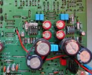
Maybe this will help. It's not my player but it shows the opamps in place. You can see the "D" cutout on the chips and also on the diagram on the board.
Lee.
Thomo said:Hi. Did you compare with the KI to ensure you connected the toroid wires correctly?
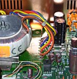
If not, I have attached a pic which may help (it's a bit low qual tho'). Check fuses also.
Lee.
Thomo(or anybody),
you'd make me so happy with this pic in somewhat higher resolution.
(I've a brown wire coming out of the TX, can't see it on the pic?)
I marked the order in which the wires came of the KI TX, but this looks different? 🙄
Thanks thomo but that doesn't really help since the placement of the opamps on the 67 is totally dif.!
The opamps placement on the 63 and 67 are the same! Everything from the DAC to the RCA ouyput is identical.
The pcb has the ic drawn on it with the cut out that matches the cutout on the opamps.
Brent
The pcb has the ic drawn on it with the cut out that matches the cutout on the opamps.
Brent
Thanks B. It's a visual thing then. I can't see very clearly in this photo. By the way, to avoid me having to ask this again or do it, did you put the coupling caps on the op amps when you changed them?
To be honest I never found any benefit fitting coupling caps. This may be due to using Black Gate caps locally.
So no I never fitted any.
Brent
So no I never fitted any.
Brent
Paulus1981 said:
pic in somewhat higher resolution.
? 🙄
This is the best I can do....
Also, there are a couple of links on the board before the toroid. You should defo check these to make sure they match the ki board.
I THINK I removed u247 & added u248. u249 should be in as should: u242 to u246.
Just compare the boards closely...
Lee.
Attachments
Brent, while I have your attention , what do you think of my thought above about the "problem" and how to solve it? Where can I source a new laser/sled/mech.?
, what do you think of my thought above about the "problem" and how to solve it? Where can I source a new laser/sled/mech.?Ok, so I did the coax mod. Now the disc spins out of control. I put everything back the way it was, but no change.
Any ideas anyone?
Lee.
Any ideas anyone?
Lee.
Somewhere along the way you've lost the clock signal to the decoder (SAA7***). It could be as simple as your clock (if aftermarket) being slow to start-up.
Hi Martin. The only coax I ran was from u100 on the rf board to r501 on hf circuit. Should be very simple.....
The first time I did it the disc span madly. So I changed the rf board for another and it worked again. So obviously I had to have another go. Same thing happened.
I am now stuck!
Lee.
The first time I did it the disc span madly. So I changed the rf board for another and it worked again. So obviously I had to have another go. Same thing happened.
I am now stuck!
Lee.
Thomo said:Hi Martin. The only coax I ran was from u100 on the rf board to r501 on hf circuit. Should be very simple.....
The first time I did it the disc span madly. So I changed the rf board for another and it worked again. So obviously I had to have another go. Same thing happened.
I am now stuck!
Lee.
Well it looks like you took it from the right place... though it's easy to have a strand of the braid touching something. Check the resistance between HF and ground.
The only thing I will say at this point is you should only ground the coax at one end. If you ground it at both ends, any potential difference in the two grounding points may cause ground currents to flow in the shield.
Thomo said:
This is the best I can do....
Also, there are a couple of links on the board before the toroid. You should defo check these to make sure they match the ki board.
I THINK I removed u247 & added u248. u249 should be in as should: u242 to u246.
Just compare the boards closely...
Lee.
Thanks a lot, this picture is quite clear (although it seems to be of another player?) Several colors differ but all the different windings (and therefore voltages) are the same.
I've checked al links between the 220 connexion and the TX, they are the same, I measure 220 volts at the TX I've also checked the two fuses, measure 9 volts at both sides of 'em.
* I still measure arround 29 volts at U311 and U312, can anybody confirm that this is correct, or?
* At which other points can / should I meassure voltages to check?
Please help me out, I miss my music

Paulus1981 said:
Thanks a lot, this picture is quite clear (although it seems to be of another player?) Several colors differ but all the different windings (and therefore voltages) are the same.
I've checked al links between the 220 connexion and the TX, they are the same, I measure 220 volts at the TX I've also checked the two fuses, measure 9 volts at both sides of 'em.
* I still measure arround 29 volts at U311 and U312, can anybody confirm that this is correct, or?
* At which other points can / should I meassure voltages to check?
Please help me out, I miss my music
Check for AC between those two points. They are the VFD heater supply. Check D851, D852 and D854. (Short=dead.) Try to measure what's going into Q851 and coming out. (7918 reg). There should be about 24-25v coming out as there is a 6.8v zener lifting it from gnd. Careful not to short anything and blow up that nice TX!
The voltages coming out of that winding (if properly connected) should be 3.5VAC, floating at -19.6VDC. You have to be clear about what you're measuring.
If you've checked the fuses for the 5V lines are intact, what AC do you get between the two? If it's not around about 9.3V, take out BOTH fuses and measure again for the unloaded figure.
What do you get going into the op-amps?
The AC and pre-regulated DC voltages in the service manual are a guide based on the basic bog-standard transformer, not KI toroid. They may be a bit different, and also vary for someone on 220V compared to 240V, etc... The only important thing is that they are not too low as prevent regulation and not too high as to overheat the regs, VFD etc.
Good luck!
Hello Gents,
I have returned after purchasing a CD53 from EBay to fix my 63KI Sig and guess what....it doesn't work, despite me confirming with the seller that it did and depiste him photographing an operational unit.
I received a message from him basically along the lines of, 'you bought it, too bad'.
I am going to have a try to see if I can get it to work before I report the guy (and even if I do I'll probably report him).
I have probed under the hood and have found that the 7812 and 7818 regs are right, but the 5V reg is only putting out 0.35V. The diodes before the 5V reg all have 27Vac across them. I haven't checked C813 yet, but plan to do so.
Is it likely that the reg is stuffed, or could it be something else (hopefully simple)?
Thanks,
Simon (Oz)
YoungSC said:I received a message from him basically along the lines of, 'you bought it, too bad'.
What a cheeky son of a...

I've just had a bad Ebay transaction, after years of almost nothing going wrong. Some people are just dishonest, plain and simple.
YoungSC said:Hello Gents,
I have returned after purchasing a CD53 from EBay to fix my 63KI Sig and guess what....it doesn't work, despite me confirming with the seller that it did and depiste him photographing an operational unit.
I received a message from him basically along the lines of, 'you bought it, too bad'.
I am going to have a try to see if I can get it to work before I report the guy (and even if I do I'll probably report him).
I have probed under the hood and have found that the 7812 and 7818 regs are right, but the 5V reg is only putting out 0.35V. The diodes before the 5V reg all have 27Vac across them. I haven't checked C813 yet, but plan to do so.
Is it likely that the reg is stuffed, or could it be something else (hopefully simple)?
Thanks,
Simon (Oz)
The reg could be stuffed, but more likely it's actually shutdown because something downstream has gone bad. It's not a big deal to swap it though to make sure.
This is assuming you've checked the fuses.
- Home
- Source & Line
- Digital Source
- Marantz CD63 & CD67 mods list