Forgot to mention i also changed the dac clock for the flea.
I removed CD02/03, RD02 and XD01. Connected clock signal to pin 28 of DAC through nearest pin of u209 which I also removed and GND in negative pin of CD04.
btw, i'm still looking for what's wrong
I removed CD02/03, RD02 and XD01. Connected clock signal to pin 28 of DAC through nearest pin of u209 which I also removed and GND in negative pin of CD04.
btw, i'm still looking for what's wrong
the green led on the flea is never on XD
It gets its 18V from an added psu, but it seems ok.
Got to check the flea then.
It gets its 18V from an added psu, but it seems ok.
Got to check the flea then.
Last edited:

green LED now lights on. 😀
but... lens is not moving at all anymore. It's in the middle of its run, and doesn't come back to start.
If I put a disc, it doesn't spin. It used to before I fixed the flea ( C4 was badly soldered)
but... lens is not moving at all anymore. It's in the middle of its run, and doesn't come back to start.
If I put a disc, it doesn't spin. It used to before I fixed the flea ( C4 was badly soldered)
Last edited:
Uh oh...
Let's see, do you have:
- about 14V at pin 7 of the AD797 ?
If not, check the orientation of R2 and R8 on the back. They have to be mounted 'North-South' and not 'East-West'.
- about 2V at pin 3 of the AD797 ?
If not, check R3 and R4. These should both carry 2V, they transport the 2V reference voltage from the LED to the opamp.
I've got 13.74V hereUh oh...
Let's see, do you have:
- about 14V at pin 7 of the AD797 ?
1.92V here- about 2V at pin 3 of the AD797 ?
And I double checked L1 : 4.94V
I must have been too tired yesterday evening, didn't check that one correctly 😱
I also checked the output of the clock : 3.35V says my multimeter when the flea is not connected to anything.
drops to 1,something V when soldered to the player pcb.
Also, the lens keep still when i power on the pcb, but if i touch, the clock output with my multimeter probe (not even the ground with the other probe) then the lens move to end of disc and tries to go beyond.
Does it mean the flea is OK ?
Thanks for your help everyone btw !
Last edited:
I did a last test, with the front pcb : it opens the tray when asked, but disc or not, it always says DISC. But disc don't spin and lens keep still.
I've done what i should have tried earlier when the clock was mentionned. I've put the original one in place (happy to have another player still fully original, I just had to compare my removed parts lot with the one in that one), powered on : the lens came back to its starting place and the disc spinned.
So there's something wrong with my flea board clock.
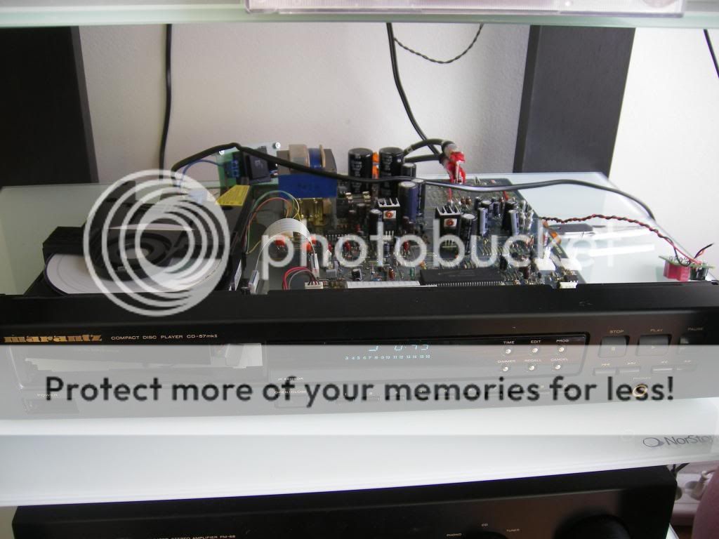
Then I wanted to give a shot just to be sure everythings fine :
here's my marantz cd57 ghetto style setup 😛
So there's something wrong with my flea board clock.
Then I wanted to give a shot just to be sure everythings fine :
here's my marantz cd57 ghetto style setup 😛
What you need to do is to buy a 50VA 2X12V toroidal transformer. Now look at the circuit diagram of the CD63. Disconnect the stock transformer's secondary winding from U308(12V), U309(earth) and U310(12V) and replace them by the 50VA Tx. You should also change C813 to a bigger cap. say 10000UF to 22000uF. For C814 change it with a 6800uF or 10000uF cap.
You may wish to see the photo in my thread 19085 for reference: http://www.diyaudio.com/forums/digital-source/54009-marantz-cd63-cd67-mods-list-1909.html
Here you can find the service manual if you don't have it: Ray's Audio Page
With a bigger Tx when the CD drive is run the voltage drop from the Tx output is around 0.5V but with the stock Tx you will find that the voltage can drop by almost 5V. Once a new Tx is fitted you will hear a tighter bass and the LF is much more extended. Worth a try and it is not that difficult 😀
I ve got the Tx but I'm not sure how to install it properly. It's this one:
http://www.amplimo.nl/images/downloads/ds standardrange/18612.pdf
Do I connect them parallel? Red + blue on U308 and yellow + grey on U310. Where do I get de earth from? I don't need a fuse before the Tx, do I?
Do I have to change the C813 cap (22.000uf Pan. TSUP 16V) to a 25V type, or will this work fine?
I've got 13.74V here
1.92V here
And I double checked L1 : 4.94V
I must have been too tired yesterday evening, didn't check that one correctly 😱
I also checked the output of the clock : 3.35V says my multimeter when the flea is not connected to anything.
drops to 1,something V when soldered to the player pcb.
Also, the lens keep still when i power on the pcb, but if i touch, the clock output with my multimeter probe (not even the ground with the other probe) then the lens move to end of disc and tries to go beyond.
Does it mean the flea is OK ?
Thanks for your help everyone btw !
Ok, so the 5V is there, that's good. But the output should measure around 2.5V with a DMM. Are you sure you have put the oscillator on correctly?
Ray
2.5V in which case ? when in the cdp or when not connected at anything, or always ?
edit: I've looked at it twice, and one solder may have looked bad. I've redone it. Now both outputs give 2.39V
I'm gonna put it back in the player and see.
edit: I've looked at it twice, and one solder may have looked bad. I've redone it. Now both outputs give 2.39V
I'm gonna put it back in the player and see.
Last edited:
Doesn't matter, it should read about 2.5V in both cases, maybe a bit less. But 1V is much too low. Do you have an oscilloscope at your disposal?
One thing i'm just figuring: did you put the 33 ohm resistor in the right place, for the output you want to use?
Ray
One thing i'm just figuring: did you put the 33 ohm resistor in the right place, for the output you want to use?
Ray
It works !
See my edited post above.
The flea was my first attempt at soldering. Well seriously soldering I mean. Two bad solder on it 😛
I just put everything back in the box, a bit heavy now, and fired one of the CD I listen to when wondering what improvement I may found.
Damn, the clock upgrade is great. One of the best improvement with the bigger caps in the power section.
Thanks everyone for your support !
Last edited:
That's great! I'm glad you like it.
For a first serious soldering job you didn't do bad at all, with the small SMD's and everything.
Ray
For a first serious soldering job you didn't do bad at all, with the small SMD's and everything.
Ray
- Home
- Source & Line
- Digital Source
- Marantz CD63 & CD67 mods list