In the UK we use 220V and I know in the US it is 120V.Thanks,
Here in the USA we use 120V, 60Hz so do not think it would work for me.
What AC voltage is used in the UK?
Don't worry about the input voltage, normally the primary winding of a transformer has 2 sets of inputs, i.e. 120V X 2. If you use one of them the input will be 120V and if you connect them in series then you will have 240V. With the correct input voltage you will get the same output secondary voltage.
However if you use a 240V transformer in the US you will only got half of the output voltage 😱
hello everyone! this is my first post to this forum.
my name is nick.
after reading... a small part of this thread, i decidet to present my "just a little" moded cd 67se. it has some caps changed with tantalum, some better regs and single op-amps. the next step is to change the supply caps (they are on the way), and... i hope a superclock. the problem is with the money, and... a superclock costs some. the question is: is there a way to find a schematics to build it myshelf?! i asked google, and did not find anyhting. or, i searched the wrong way. if somebody has a schematics to share... i'll be glat to receive it.
the hdam is still operational, but i think i'll do some tests without it.
next days i'll try to share some pics from the moded 67 inside.
so.... any advice is welcome.
Hi Nick,
Go for the Flea : ask Ray about it.
The PFM Flea
cheap and a great clock.
Last edited:
Depending on how fussy you are and whether you're trying to keep costs down, you can also use these:Higlander,
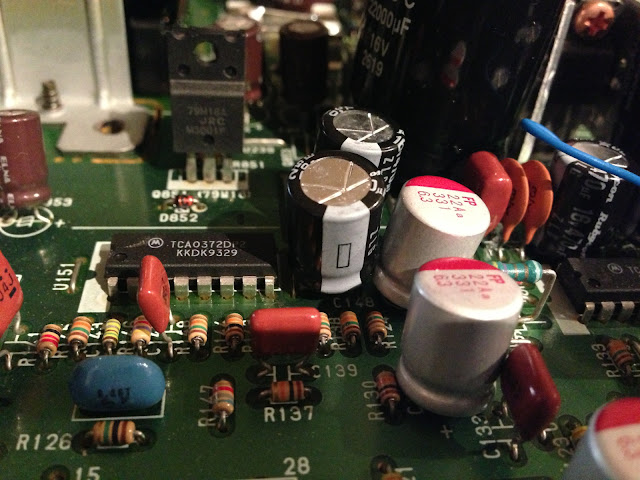
I have checked your pcb to establish where you have placed the Oscons, and have come up with this list:
DAC: CD04, CD07
Decoder: C510, C511
Servo: C120, C122
RF: C504
C124, C134
C106 (on tray pcb)
I also looked on Brent's page and his list comprises: CD04, CD07, C510, C511, C120, C122, C504
+ 1 to go on output of reg (HF) – R107?
I make that 11 in total (If I include both lists). Am I correct in this respect?
Also, are these the correct ones:
Buy Aluminium Capacitors OSCON 105 SMD 470uF 6.3V, 6SVP470M Sanyo 6SVP470M online from RS for next day delivery.
Sorry for the oodles of questions. Your help is appreciated... many thanks.
Buy Aluminium Capacitors Solid Al cap Radial NS series 6.3V 330uF Nichicon RNS0J331MDN1PH online from RS for next day delivery.
Which are the same Solid Polymer construction and very similar specs, but much cheaper.
I followed Ian's advice and used these Nichicon NS instead of the Oscons and whilst I haven't compared both like for like, I'm happy with the results 🙂
One thing that confused me with the list above was that C134 as standard is a 50v rated cap 😕
They are all correct and you got 100% mark 😉😉
Brill! Many thanks... and where is my star? 🙂
Depending on how fussy you are and whether you're trying to keep costs down, you can also use these:
Buy Aluminium Capacitors Solid Al cap Radial NS series 6.3V 330uF Nichicon RNS0J331MDN1PH online from RS for next day delivery.
Which are the same Solid Polymer construction and very similar specs, but much cheaper.
I followed Ian's advice and used these Nichicon NS instead of the Oscons and whilst I haven't compared both like for like, I'm happy with the results 🙂
One thing that confused me with the list above was that C134 as standard is a 50v rated cap 😕
Thanks for the heads-up on this. I might stick with the Oscons (a case of 'I must have the Nike trainers!'). Just 1 point: the ones you mention are a different uF value. Will this make a difference? I am not competent enough to answer this question.
Also, your point about C134 being a 50V cap is beyond me. Perhaps someone else could help here.
Any solid polymer cap will be better than standard oscons on digital rails due to the incredibly low ESR/ Impedance.
For my own stuff where I'm not so concerned about cost, I'll use OsCon SEPC's which are pretty amaizing.
I have 1 or 2 on my SA7001 transport! 😀


For my own stuff where I'm not so concerned about cost, I'll use OsCon SEPC's which are pretty amaizing.
I have 1 or 2 on my SA7001 transport! 😀
The Oscons in the link you have provided are surface mount caps and be sure you know how to replace the stock caps with them 😉Thanks for the heads-up on this. I might stick with the Oscons (a case of 'I must have the Nike trainers!'). Just 1 point: the ones you mention are a different uF value. Will this make a difference? I am not competent enough to answer this question.
Also, your point about C134 being a 50V cap is beyond me. Perhaps someone else could help here.
IMHO using 330uF or 470uF caps makes almost no difference at all.
For C134 I think a 16V cap is good enough as the supply voltage to the IC is only 10V.
Any solid polymer cap will be better than standard oscons on digital rails due to the incredibly low ESR/ Impedance.
For my own stuff where I'm not so concerned about cost, I'll use OsCon SEPC's which are pretty amaizing.
I have 1 or 2 on my SA7001 transport! 😀
Nice work and for me I also prefer using OsCon SEPC.
Nice work and for me I also prefer using OsCon SEPC.
Just done a quick search and I cannot find a source of Oscon SEPCs in the UK (other than surface mount). Where do you get them from in the UK?
I found this seller in China:
14pcs 470uF 6 3V Sanyo Sepc OSCON Aluminum Solid Capacitor 8x12mm | eBay
Thanks
Just done a quick search and I cannot find a source of Oscon SEPCs in the UK (other than surface mount). Where do you get them from in the UK?
I found this seller in China:
14pcs 470uF 6 3V Sanyo Sepc OSCON Aluminum Solid Capacitor 8x12mm | eBay
Thanks
Don't buy posh capacitors on eBay from the Far East, there are loads of fakes.
I'd try Farnells, or failing that, Digikey in the USA have basically everything you could ever want and can have it with you in 2 days if you can stomach the 15 quid delivery and import duty
Don't buy posh capacitors on eBay from the Far East, there are loads of fakes.
I'd try Farnells, or failing that, Digikey in the USA have basically everything you could ever want and can have it with you in 2 days if you can stomach the 15 quid delivery and import duty
Hi, Thanks for the tips... just tried Farnell and Digikey (UK and USA), but no luck unfortunately.
Hello,
if somebody can give me a tip!
After I unite instructions to Ray's
Mods has made is a problem with the
IR Receiver appeared.
I can serve the player only from 10 cm of distance over the remote control.
Does somebody have an idea where the mistake is?
Hi Fredi,
Did you put an electrolytic on the front panel board, across CY01? It's near the infra-red receiver. Any cap between 10...47uF will do. That will solve your problem!
Ray
Hi,
That's the idea indeed 🙂
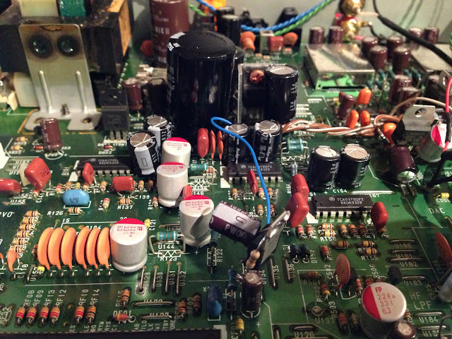
If thing get really tight, you can move some small ceramics to the back of the board, but if you leave the electrolytics a few mm from the board, it fits nicely.
Here's a picture of how I did it. I didn't use separate regulators for each driver, but replaced U234 and U237 with regulators later on.
Regards,
Ray
Thanks Ray, I got them in nicely with a bit of leg bending
and some X7R on the back

I like the idea of just using 1 positive and 1 negative regulator for the 3 drivers using U234 and U237 and I understand I need to cut and rejoin to U161 so that it's included correctly.
But I'm unsure about what to do with the resistors if I'm doing this?
R127 & R128, R149 & R150, R164 & R165
Should I leave them, bridge them or replace them with something else?
thanks again,
James
Last edited:
Hi James,
Nice work!
Those resistors are very low in value, so they won't cause much voltage drop. They are there to act as fuses, just in case a driver burns out. I would leave them in place. The regulator will take care of the seriously large voltage fluctuations, so that's fixed.
Ray
Nice work!
Those resistors are very low in value, so they won't cause much voltage drop. They are there to act as fuses, just in case a driver burns out. I would leave them in place. The regulator will take care of the seriously large voltage fluctuations, so that's fixed.
Ray
thanks 🙂
Next job is to install the 50va Tx, but I didn't realise that the 22,000uf STUP cap I just fitted on the +10v rail is only 16v, so I have to delay a little while I get a replacement..
Next job is to install the 50va Tx, but I didn't realise that the 22,000uf STUP cap I just fitted on the +10v rail is only 16v, so I have to delay a little while I get a replacement..
Hi
I need some help.
So far I've followed Ray modding list for my CD57..
Today I've done the last thing left :
Decoder (Q102, SAA7372GP)
part ref | original part | new part
C108 | 100n cer. | 100n MKT
C109 | 22n cer. | 100n MKT
C110 | 47p cer. | 47p PS
C114 | 47u/16V | remove
C115/117...119 | 47n cer. | 100n PPS
C116 | 47n cer. | 220u/16V
C120 | 47u/16V | 220u/16V
C125 | 1n cer. | 1n PS
R117/118 | 4,7R | 220uH/3R3
μController (QF01, MN187164)
CF02 | 47u/16V | remove
CF01 | 47n cer. | 220u/16V
CY01 | 47n cer. | 22u/16V in parallel
RF01/RY11 | 4,7R | 220uH/3R3
Now when I power up the player, the lens is going crazy.
At first I tought I forgot to plug JW01, as it once happened, but it's well fitted.
What could I check ?
Last edited:
I suspect there is an error in the parts around the decoder. I suggest you check your last work, the polarity of the electrolytics and look for broken pads, bad connections or solder splashes that may cause the problem.
Ray
Ray
I've put C116 and C120 as seen here : www.raylectronics.nl/pictures/cd67/CD57_Overview.jpg
I'm trying to remove and redo every cap and test one after one.
I guess JW01 and J103 are the only two needed to be plugged in order to check, am I right ?
I'm trying to remove and redo every cap and test one after one.
I guess JW01 and J103 are the only two needed to be plugged in order to check, am I right ?
Get one of these.
Mini Pocket LED UV Jewellers Loupe 60x Microscope Glass Jewellery Magnifier Z34 | eBay
Just because you can't see it doesn't mean it's not there!
Mini Pocket LED UV Jewellers Loupe 60x Microscope Glass Jewellery Magnifier Z34 | eBay
Just because you can't see it doesn't mean it's not there!
Dunno, I guess you need JM02 as well to let the player know the tray is closed.
The front can remain unconnected AFAIK.
The front can remain unconnected AFAIK.
- Home
- Source & Line
- Digital Source
- Marantz CD63 & CD67 mods list