adfinni said:Thanks a lot guys
Ive just wacked on teh iron and am going to have a play 🙂
beware of drunk student with hot soldering iron

ray and andy's posts are the ones to start with.
allan
poynton said:
Typical student - if in doubt, get drunk !
As always. But i didn't tonight, like i though i would
First check these voltages :-
across C122 - should be +5v
across C124 - should be +2.5v
across C148 - should be -12v approx. [pin 9-16 on Q106]
also from either end of R128 to ground [0v] - as above
Check carefully for shorts / solder splashes around the 2 jumpers [U139 / U140 ]
U139 connects the sled signal from the servo chip [Q104] to the sled driver [Q105]
All of those were fine. I put u140 back in with its jumper, and used some of my standard silver plated copper wire to bridge back u139.
It also looks like you may have a few dry joints !
You can always send it to me to fix but where's the fun in that?
What exactly is a dry joint, and do i have to remove all the old solder and apply new stuff. I managed to steal some leaded solder from a lab at uni, so im using that at the moment as it is great to work with.
And i have just removed the clock now and will clean up the joints and resolder on new wire asap.
I might be tempted to send it to you mate, as i have far too much work to do, rather than trying to fix this, but il see how it goes😀
allan. When i power up the player, the clock psu voltage jumps straight up to its value of 9.8V, and there is no delay. Only thing is that i couldnt get a reading for the clock output. it just kept jumping from a low value to a negative value off the scale (like a pulse). i guess thats the oscillating part of the clock ?
silly silly cdp
thanks
adfinni said:
As always. But i didn't tonight, like i though i would
All of those were fine. I put u140 back in with its jumper, and used some of my standard silver plated copper wire to bridge back u139.
What exactly is a dry joint, and do i have to remove all the old solder and apply new stuff. I managed to steal some leaded solder from a lab at uni, so im using that at the moment as it is great to work with.
And i have just removed the clock now and will clean up the joints and resolder on new wire asap.
I might be tempted to send it to you mate, as i have far too much work to do, rather than trying to fix this, but il see how it goes😀
allan. When i power up the player, the clock psu voltage jumps straight up to its value of 9.8V, and there is no delay. Only thing is that i couldnt get a reading for the clock output. it just kept jumping from a low value to a negative value off the scale (like a pulse). i guess thats the oscillating part of the clock ?
silly silly cdp
thanks
dry joint
solder joints should be shiny, (look wet)
if dull and crows-feet(cracks) maybe bad joint
clock supply should be +5v
are you using a tent clock module and the 8 pin socket?
if so, unplug the clock
pin 8 should be +5v appox on the socket
referenced to grd
then switch off player leave for a few minutes and then plug in clock
ps tent clock is dot is pin 1, first "T" of TENT is pin 8
sometimes it is best to remove old solder.
if you have a big bubble of solder then its too much
allan
Hey allan
awpagan said:
dry joint
solder joints should be shiny, (look wet)
if dull and crows-feet(cracks) maybe bad jointOk then, il have to re-solder all the main bits, just to be sure 🙁
clock supply should be +5v
are you using a tent clock module and the 8 pin socket?
if so, unplug the clock
pin 8 should be +5v appox on the socket
referenced to grd
then switch off player leave for a few minutes and then plug in clock
ps tent clock is dot is pin 1, first "T" of TENT is pin 8allan
Take a look on page 132 of the thread, and you will see some pics of my clock and psu.
I have the audiocom superclock 2, and a custom PSU made by andy.
This wsa the first mod a id a few months ago, and it was working swimmingly, the only reason why i thought the clock might be the problem is that the hot glue that used to hold it down, came loose whilst i was putting in all teh mods a few days ago, so the **** was hanging around in mid air, or rubbing against the board or my foam work surface. I hope it isn't too delicate and i have busted it.
Well when i fiddled around yesterday the clock output seemed to be jumping around in a pulse type way, going from a reading of just above 0v, to crazy -ve readings way off the scale, every half a second or so. Does that mean it's working ?
thanks
ad
adfinni said:
..............the **** was hanging around in mid air, or rubbing against the board or my foam work surface. I hope it isn't too delicate and i have busted it....................

A little edit required ?
adfinni said:
.......... some leaded solder ..............
Is it electrical solder?
Maybe a visit to your local Maplin's for a small tube of solder and a roll of solder wick is called for.
The joints around the +-10v supply look 'dry' in your photos.
I use Meths on a cotton bud to clean up before and after soldering - the above shop sells solvent cleaner N69AN or N64AN
Andy
adfinni said:
All of those were fine. I put u140 back in with its jumper, and used some of my standard silver plated copper wire to bridge back u139.
Silver requires silver solder for a 'good' joint.
Are all the voltage checks I suggested OK ?
awpagan - the psu voltage is correct. It feeds the clock module which has an onboard 5v regulator.
Andy
poynton said:
across C122 - should be +5v
across C124 - should be +2.5v
across C148 - should be -12v approx. [pin 9-16 on Q106]
also from either end of R128 to ground [0v] - as above
Check carefully for shorts / solder splashes around the 2 jumpers [U139 / U140 ]
U139 connects the sled signal from the servo chip [Q104] to the sled driver [Q105]
Andy
Hey andy.
All of those voltages listed above were fine. If the silver plated copper wire i use ideally needs silver solder, then would it be better for me to use cat5 cable instead with my standard leaded solder.
One thing, could the removal of u139/140 then the switching on of the player caused some damage, as that was the first thing i did about a week ago whilst i was strengthening my chassis. I didn't put those two back in until the other day?
thanks
adfinni said:
All of those voltages listed above were fine.
Hi.
In your previouspost, you gave the voltage for Q105, pins 9-16, which were low [7v]. The voltage either side of R128 should be around -12v, the same as pins 9-16. If they are different, it indicates a fault between R128 and Q105.(which is impossible given the distance. So your original voltages would seem to be in error
If the silver plated copper wire i use ideally needs silver solder, then would it be better for me to use cat5 cable instead with my standard leaded solder.
Yes
One thing, could the removal of u139/140 then the switching on of the player caused some damage, as that was the first thing i did about a week ago whilst i was strengthening my chassis. I didn't put those two back in until the other day?
thanks
Q105 is the driver for the sled and the laser.
U139 feeds the drive signal - removing it would give +5v on the input causing the sled to move to one extreme.
However, removing U140 disconnects the sled from the drive [leaving the feedback loop intact] which would mean that the sled would not move [no drive].
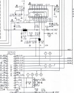
The black blobs on the attached show the position of the links.
What worries me is :-
you said with the links removed the sled went to one end.
with them replaced, it went to the other end.
The voltages around the chip are wrong.
Recheck the voltages around the chip [you can disconnect the cdm] should be as per diagram.
Clean up soldering.
Andy
Attachments
..............the **** was hanging around in mid air, or rubbing against the board or my foam work surface. I hope it isn't too delicate and i have busted it....................
HAHA. That one missed (l) made it sound very dirty 😀
Il redo my soldering and see what happens. Hopefully it is just a dry joint causing all of this, but we'll see.
Il have a play later today and tomorrow.
ad
adfinni said:
Il have a play later today and tomorrow.
What are you going to play with?

OK, tonight I performed the next steps in modding my cd67se.
I already removed the output caps and muting trannies and damped the chasis with bitumen.
* Replaced the opamps with AD826's.
* Bypassed HDAM.
My first impression is that the bass is much deeper now. Overall impression is that the "stage" is bigger.
Only downside is that the highs have become harder, maybe that has to do with the AD826'S?
gy21 said:Only downside is that the highs have become harder, maybe that has to do with the AD826'S?
That's very well possible, I found this opamp to be quite upfront, with lots of treble, in-your-face so to speak. You may try some decoupling directly at the PSU pins (4 & 8). Or AD8620 🙂
Ray.
the AD8620's are on it's way, btw some people complain that the ad8620 sound "thin".
I heard about decoupling opamps from pin 4 to 8, what value would you recommend?
Anyway the cd67se sounds already way better then before I started the mods.
Tent clock is also ordered. After that i will play with some decoupling of caps and that is probably as far as i go.
I heard about decoupling opamps from pin 4 to 8, what value would you recommend?
Anyway the cd67se sounds already way better then before I started the mods.
Tent clock is also ordered. After that i will play with some decoupling of caps and that is probably as far as i go.
gy21 said:the AD8620's are on it's way, btw some people complain that the ad8620 sound "thin".
I agree with that, a bit. It sounds WAY better compared to the standard 2114's, no doubt about that, it's a very nice sounding opamp. But maybe a dual one is a bit too much. So I tried a single AD8610 after the DAC, and a different one in the filter (using an adapter), like OPA132 or OPA627. It takes away a bit of that "thin" edge.
I heard about decoupling opamps from pin 4 to 8, what value would you recommend?
I use a 220n PPS SMD cap most of the times. But you can use a good small electrolytic (BG) if you have that around. Or do the DeLuxe version and decouple from + and - to 0V.
Regards,
Ray.
ray
this site has some usful info on opamps
also bias to class A
http://tangentsoft.net/audio/opamps.html
allan
this site has some usful info on opamps
also bias to class A
http://tangentsoft.net/audio/opamps.html
allan
6h5c said:
I use a 220n PPS SMD cap most of the times. But you can use a good small electrolytic (BG) if you have that around. Or do the DeLuxe version and decouple from + and - to 0V.
Regards,
Ray.
I have no BG around, will another electrolytic do? and what about a small fim cap?
Do you decoupling to every opamp type of opamp in that position, or are only certain models benefitting from it?
awpagan said:ray
this site has some usful info on opamps
also bias to class A
http://tangentsoft.net/audio/opamps.html
allan
Hi Allan,
I have that one in my bookmarks list already, very useful site, thanks anyway 😉.
I still have to try that class-A....have to make a to-do list for those things, I keep forgetting it.
Ray.
- Home
- Source & Line
- Digital Source
- Marantz CD63 & CD67 mods list