I would say the resistor will be ok. It is a 2w Kiwame, and they're built for ruggedness.
Lee
Lee
Well Lee, I will keep it as is.Thomo said:I would say the resistor will be ok. It is a 2w Kiwame, and they're built for ruggedness.
Do you believe the heat does not affect the caps sonically ?
Ricardo
RCruz said:
Well Lee, I will keep it as is.
Do you believe the heat does not affect the caps sonically ?
Ricardo
Nope. My FK run warm, not hot but warm. You do have all the polarities right don't you?😀
Lee.
Hi Ray,
Thanks for your reply
On the SAA7323 data sheet, pin 23 on supplies +5V to the "crystal oscillator power supply." However, I have replaced the crystal with a Tent XO oscillator and its own power supply. Does this mean that pin 23 is now redundant?
I have some 470uH/2.5R Epcos inductiors so I will use one of those.
Is 220uF 6.3V Os-con overkill for this application? I have a few on hand.
Cheers,
Joe
Thanks for your reply
Pin 23 probably supplies the internal inverters, and some extra decoupling reduces noise in the other power line.
On the SAA7323 data sheet, pin 23 on supplies +5V to the "crystal oscillator power supply." However, I have replaced the crystal with a Tent XO oscillator and its own power supply. Does this mean that pin 23 is now redundant?
If you use a small 470uH...1mH inductor that has some DC resistance (like the 1mH/10R from Epcos), you don't have to use the parallel resistor.
I have some 470uH/2.5R Epcos inductiors so I will use one of those.
Is 220uF 6.3V Os-con overkill for this application? I have a few on hand.
Cheers,
Joe
Thank you Lee.Thomo said:
Nope. My FK run warm, not hot but warm. You do have all the polarities right don't you?😀
Everything is correct.
As soon as I get the hookup wire from AE Europe, I will place the DOS in the CDP.
Regards
Ricardo
mm2 said:
Yes, the point of reference is very important, but where ist this point of reference ? I think there are many :-(
In the original player the point of reference for the analog signal is near the RCA Sockets. But this point is far away from the DAC,
so there is a long run of wire to the DAC and the connection between clock and analog, which is the point of reference for the DAC.
This reduces jitter like you explained, but the current from clock and analog uses the same long ground wire. This current noise you will find at the RCA socket :-(
OK, lets start from the top:
The reference for the analog DAC stage (careful - NOT the analog output stage of the whole CD), i s the analog ground pin(s). If you have a separate regulator for this, ideally it's return ground should go as close to the pin as possible, togethr with the actual ground wire. Similar thing with the analog power supply wire, and return if available (for instance if you use a super-regulator with return pins).
However, this is usually overkill - especially if the lines are long. They may pick up stray RF and actually make matters worse. This is why local desoupling caps are used - again, as close to DAC pins as possible. These represent a very low impedance across analog Vcc and GND, which in turn makes the connecting power supply wires, a aprt of a filter (RLC). In fact, it is often customary to deliberately include series resistors - his not only dampens the RLC combo, but also decreases cut-off frequency of the filtr towards DC, and limits AC currents 'inside' the caps - because that impedance is lower than the series resistors. Of course, this is best done for laods that have a constant current draw.
The important thing to note here, is that the series resistor actually 'removes' the power supply or ground lines from being a part of the reference point, and instead forms a local reference point, at the node of least AC impedance. In practise, this 'node' will rarely be a single point, but often a larger part of the PCB because components do have their dimensions and can only be packed so close together.
Exactly the same thing happens with the clock power supply and ground. The reference of the circuit are the actual chip pins.
Now, things get complicated because the clock and analog GND should be as closely tied together as possible - in fact, ideally, at one point (this is why some low pin count DACs combine the analog and clock ground in one pin). Again, this is because any sgnal injected between the clock and analog grounds directly produces jitter. Unfortunately my scanner is dead, so I can't put up a simple sketch showing how this happens.
The analog CDP output reference is at the output connector, because this is the shortest path to the output current loop. The output stage pushes or pulls current from the +-12V power supply into the load, and back into the ground return, which is connected to the return point of the regulators (separate ground return at the output conenctors). This is the local star ground for the analog output stage.
Again, ideally, it should tie in one point with the analog DAC output ground pin and clock ground pin, but in reality these points are far away so proper star ground can't be used. Instead, you attempt to take asm much AC current out of the line connecting the output conenctor ground and the DAC analog ground. This is wht the ground return is from teh output connector - the output currents are much higher than the input currents into the output stage OPamps. Additionally, because we want the output AC currents to stay in a small area on the baord around the actual output, the output OPamps have RC filtered power supplies (10 ohms and 470uF). The point of this is that for AC the 470uF cap represents a much lower impedance than the 10 ohm resistor, so the AC loop current stays within the cap, OPamp and load. As long as any ground references for the OPamp (which are generally low current, i.e. signal grounds) are connected to a point so that the output current does not create different voltage drops between them, you have created a locak ground reference.
Generally in electronic circuits with more than one stage (which means, a great majority), each stage has such a local reference point, or local ground. These are connected in a single line from the point of highest current (output) to the point of lowest current, with the idea that only the coupling currents between stages flow between these points. Any voltage drop in the ground line, in such a case, just adds to the voltage drop in the signal line, as no other AC currents but signal currents flow here. The same principle is used in the CDP - the grounds go from the output, to the DAC analog output, and from there, generally to the DAC digital part and from there to all other digital parts down the line. Digital circuits are generally a bit more flexible as far as ground issues are concerned, so once you are in the digital domain, the routing can be somewhat relaxed (but traps exist here as well... like the clock issue we are discussing, which is analog, not digital).
Again, where is the best point ?
Should the sense of the regulator be connected to ground near the DAC
( to reduce jitter noise ) or near the RCA socket ( to reduce current noise ) ?
Regards
As i said, at the DAC, but beware of inductive pickup. Also, it may not be as problematic if there is local RC or LC filtering, which creates local reference points precisely to avoid reference point issues.
A good example would be my mod. Even though the analog supply for the dac is taken from the +12V of the analog output stage of the CDP, it feeds a shunt regulator through a current source. This is a very high impedance feed, which would be completely impractical if imnplemented as RC or LC filtering. The shunt regulator element (LEDs in my case) is connected as close to the DAC as the PCB would alow, and in fact has a large local decoupler cap which is even closer to the DAC so that most AC passes through it. Because the current source feed is so high impedance, the +12V error resulting from the regulators having the return point at the CDP output, instead of the DAC analog GND pin, is as attenuated as any other noise or ripple out of the regulator - by the ratio of current source impedance and shunt element in parallel with capacitor impedance. Typically this would be a good 60-80dB even with no capacitor, at any frequency up from DC (which no RC or LC filter will do). Because the shunt is fed from a constant current source, obviusly, it supresses any noise or ripple current from the power supply, trying to keep the current constant, so a local ground point is created at the DAC.
Finally, although i have not said it so far, it should be obvious that a DC current only creates a DC offset voltage between references, so does not translate to jitter or noise anywhere, which is why RC, LC and CCS+shunt filtering is used - we try to keep the current inside the wires to the power supply or regulator, as close to DC as possible.
With the SM5872 DAC, I would not feed the PWM output stage off the +12V analog supply, but that's just my opinion...
Ray
Ray
jnewbold said:Hi Ray,
Thanks for your reply
On the SAA7323 data sheet, pin 23 on supplies +5V to the "crystal oscillator power supply." However, I have replaced the crystal with a Tent XO oscillator and its own power supply. Does this mean that pin 23 is now redundant?
I have some 470uH/2.5R Epcos inductiors so I will use one of those.
Is 220uF 6.3V Os-con overkill for this application? I have a few on hand.
Cheers,
Joe
I assume you have the Tent XO connected to pin 25? And the clock signal is probably distributed to the rest of the player from pin 26. This means the internal inverter is still used, so you still have to supply power to pin 23. I would just give it a try with the components you have on hand, and see how it sounds.
Regards,
Ray
Hi ilizim,
a great great great posting, again.
thanks a lot.
Everything is correct ;-)
I'm sure this works in a wide range of frequency, from DC to ca. 200KHz,
because large decoupling caps ( like 470µF ) have there lowest impedance here.
Little low inductive foil caps have there lowest at may be 10Mhz
and bypassing or snubbering have to be done carefully.
But clock signal is a 16Mhz sqaure wave which contains a wide range
of harmonics and I am not sure that ( local ) passive or active decoupling will work
good enough ( don't know the dynamic Impedance of a led or zener diode at 16Mhz ).
Regard
a great great great posting, again.
thanks a lot.
Everything is correct ;-)
...
RC filtered power supplies (10 ohms and 470uF )
...
by the ratio of current source impedance and shunt element in parallel with capacitor impedance. Typically this would be a good 60-80dB even with no capacitor, at any frequency up from DC.
Because the shunt is fed from a constant current source, obviusly, it supresses any noise or ripple current from the power supply,
...
we try to keep the current inside the wires to the power supply or regulator, as close to DC as possible.
I'm sure this works in a wide range of frequency, from DC to ca. 200KHz,
because large decoupling caps ( like 470µF ) have there lowest impedance here.
Little low inductive foil caps have there lowest at may be 10Mhz
and bypassing or snubbering have to be done carefully.
But clock signal is a 16Mhz sqaure wave which contains a wide range
of harmonics and I am not sure that ( local ) passive or active decoupling will work
good enough ( don't know the dynamic Impedance of a led or zener diode at 16Mhz ).
Regard
Inductors needed?
Hi,
I have replaced the series resistors on the 5V supply lines to the DAC and Decoder with 470uH/2.5R inductors and two ferrite beads. If I install separate regulators (analogue and digital) for these chips, fed by a separate PSU and transformer, will inductors/beads still be necessary, or can I remove them when I instal the regs?
What would be the minimum VA rating required for a transformer to feed the DAC chip regulators?
Thanks, Joe
Ilimzn - this is great info. I've only just read it all as I've been away for a week.
I'm currently renovating a spare CD63 (have done CD67SE before) and will take note of these grounding issues in particular.
I appreciate your explanations of taking the clock/pwm supply from the analogue side, especially as it goes against previous recommendations.
I found that regulation the servo amps (LM317/LM337 to +/-7V) gave an enormous improvement across the board, and this is probably due to reducing servo current noise the DAC supplies (which were still being fed from the digital psu). They need heat-sinking, btw.
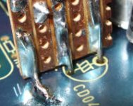
I currently have a clock supply similar to this one by Andy Weekes (LM317 on clock). He has two ground legs - one for decoupling and one for the adjust (sense gound) - but has them both tied to the gound plane. What I did was move the electrolytic to where the ceramic was and put the ceramic underneath, freeing up the electrolytic location for the LM317, giving me a +5V input feed point and access to the DAC ground. I put the decoupling ground to the ground plane and the reg output and adjust grounds through the cap holes so the sense ground is closer to the DAC. I used 120R and red+green LED to give 10ma/5V. (Attached pic is from a similar thing I did in my CD67.)
So it would be a good idea to use this regulator to feed not just the clock but also the PWM supplies, and feed it from the +12V?
But then where to attach (and/or) join the ground(s)... I can't detach the clock ground from fat ground trace under the DAC chip(unless I lift the pin or remove the DAC).
I think I need to re-read what you wrote!
I'm currently renovating a spare CD63 (have done CD67SE before) and will take note of these grounding issues in particular.
I appreciate your explanations of taking the clock/pwm supply from the analogue side, especially as it goes against previous recommendations.
I found that regulation the servo amps (LM317/LM337 to +/-7V) gave an enormous improvement across the board, and this is probably due to reducing servo current noise the DAC supplies (which were still being fed from the digital psu). They need heat-sinking, btw.
I currently have a clock supply similar to this one by Andy Weekes (LM317 on clock). He has two ground legs - one for decoupling and one for the adjust (sense gound) - but has them both tied to the gound plane. What I did was move the electrolytic to where the ceramic was and put the ceramic underneath, freeing up the electrolytic location for the LM317, giving me a +5V input feed point and access to the DAC ground. I put the decoupling ground to the ground plane and the reg output and adjust grounds through the cap holes so the sense ground is closer to the DAC. I used 120R and red+green LED to give 10ma/5V. (Attached pic is from a similar thing I did in my CD67.)
So it would be a good idea to use this regulator to feed not just the clock but also the PWM supplies, and feed it from the +12V?
But then where to attach (and/or) join the ground(s)... I can't detach the clock ground from fat ground trace under the DAC chip(unless I lift the pin or remove the DAC).
I think I need to re-read what you wrote!
Attachments
Re: Inductors needed?
Hi Joe
If you place the sregs near the DAC (you should), you can loose the inductors.
The best option for the TX is: 15VA 2x9V
Use one winding for dac analof and the other for DAC digital.
Make sure the sreg on dac analog is not noisy.
Regards
Ricardo
jnewbold said:will inductors/beads still be necessary, or can I remove them when I instal the regs?
What would be the minimum VA rating required for a transformer to feed the DAC chip regulators?
Hi Joe
If you place the sregs near the DAC (you should), you can loose the inductors.
The best option for the TX is: 15VA 2x9V
Use one winding for dac analof and the other for DAC digital.
Make sure the sreg on dac analog is not noisy.
Regards
Ricardo
If you place the sregs near the DAC (you should), you can loose the inductors.
The best option for the TX is: 15VA 2x9V
Thanks Ricardo,
My local electronucs part shop sells a 20VA toroid so I'll go for that. I plan to put the rgs right on each chip.
Joe
Hi Joejnewbold said:
Thanks Ricardo,
My local electronucs part shop sells a 20VA toroid so I'll go for that. I plan to put the rgs right on each chip.
What type of reg do you plan to use in the dac analog ?
Ricardo
ilimzn said:The problem with the original circuit is that the impedance the + and - differential PWM outputs see, is different at audio frequencies, and one of them is also highly dependant on the OPamp's open loop gain characteristics. This is because in an attempt to save on one OPamp per channel, the first two filter stages and differential to single-ended conversion have been merged into a single circuit. As a result, filtering for the + input to the OPamp is 'passive', while for the - input it is passive for the first stage, and 'active' for the second. 'Active' because for this particular circuit, a capacitor that goes to ground, forming the second stage of the filter, for the + OPamp input, ends up in the feedback loop of the OPamp, for the - OPamp input.
Couldn't one use a differential op-amp instead of two ordinary ones? And then sum the output with an ordinary op-amp?
I'm thinking something like the THS4130 or the OPA1632 as then both differential outputs would be treated somewhat more equally... or is it that these differential op-amps are still not symmetrical enough.
What type of reg do you plan to use in the dac analog ?
Hi Ricardo,
I am on a tight budget so I won't be using anything to fancy. My plan is to use either a "Rayreg" with LT version of the 317 or to spend a few more dollars and try the LT1963, which is a low noise regulator chip. I have already used the LT317 for the opamps.
Perhaps in the future I will try the super regs.
For the Tent XO clock upgrade I have a separate transformer, schottky diodes 4700uF FCs and the PSU shown on the Tent website.
Cheers,
Joe
Hi Joejnewbold said:
Hi Ricardo,
I am on a tight budget so I won't be using anything to fancy. My plan is to use either a "Rayreg" with LT version of the 317 or to spend a few more dollars and try the LT1963, which is a low noise regulator chip. I have already used the LT317 for the opamps.
I started with a rayreg in dac analog, using a 317, but when I changed to a spower reg, the difference was awesome.
The dedicated PSU for this item is also very important.
Hope you can post some pictures soon.
Regards
Ricardo
Here's a new discrete high performance regulator ..... low noise, wide bandwidth, fully adjustable and a fraction of the price of most others!
MiniReg discrete low noise regulator
I've used these and they are very good.
MiniReg discrete low noise regulator
I've used these and they are very good.
Spartacus said:Here's a new discrete high performance regulator ..... low noise, wide bandwidth, fully adjustable and a fraction of the price of most others!
MiniReg discrete low noise regulator
I've used these and they are very good.
Hi Spartacus
How can we see the pictures ?
This is very interesting indeed.... Can someone comment on the output capabilities (50mv ??)
Ricardo
- Home
- Source & Line
- Digital Source
- Marantz CD63 & CD67 mods list