rowemeister said:
Nope!!
But I am working on having my own regulators built. They will be better than the Audiocom super reg and comparable with the Qpower reg.
I have been testing the prototypes and am very happy with them, it will be using two very low noise smt opamps for the reference circuit and a fet on the output and will be on cards that are a direct replacement for a 78** and 79**. Problem is the cost as its not the cheapest in low volumes. Never mind. lol.
I'll keep people posted
Brent
Im sure i could test a load of them to destruction mate 😀
Where I can delete some old posts? Did I say it sounds not so good? It sounds soooo good!
Propellerheads "Decksandrumsandrockandroll": just had a try at track 1: OMG!

I've found a flaw, highs are a bit harsh. Maybe too many LM4562? (in amp also...) or maybe normal without clock & regs? Maybe the sound of the amp?
Propellerheads "Decksandrumsandrockandroll": just had a try at track 1: OMG!
I've found a flaw, highs are a bit harsh. Maybe too many LM4562? (in amp also...) or maybe normal without clock & regs? Maybe the sound of the amp?
Malefoda said:I've found a flaw, highs are a bit harsh. Maybe too many LM4562? (in amp also...) or maybe normal without clock & regs? Maybe the sound of the amp?
Hard to say. Try a different source with the amp, and interconnects. Harshness on the CD player can be helped with soft-recovery diodes and upgrade of the analog filtering - I don't remember what you've done. Cerafine electrolytics have a softer sound to me, or BGs can help. The LM4562 even broken in sounds clear. I would borrow another source to see if its the amp.


Hi Simon,
this sounds like you have the chassis safety earth connected to the audio ground. Am I interpreting that correctly?as it's the only earth connection to the external psu (to avoid ground loops)...
adfinni said:
Im sure i could test a load of them to destruction mate 😀
You are banned from them LMAO
only kidding
Brent
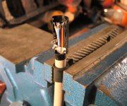
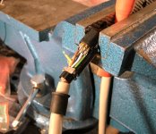
SimontY said:The "Lapp Kabel" 8 core wire is very nice. Copper braid shielded and eight distinct colours of insulation. Stranded copper. It only just squeezes into the DIN connector.
Is that your penis stuck in the vice. LOL
Brent
SimontY said:Did my psu connectors tonight 😀
Hey Simon!
Nice pictures, looks very neat. Nice connector job! I guess i'm falling behind, since my players still use the internal PSU 😀. Maybe i'm going to make one with tubes
 .
.Ray
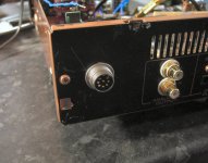
SimontY said:The red arrow points to the single grounding terminal. If this was disconnected all hell would break loose, as it's the only earth connection to the external psu (to avoid ground loops)...
Sorry for so many pictures. I guess I'm over excited!
Simon
LOL would be interesting if that fell out. Looking good though.
Brent
AndrewT said:Hi Simon, this sounds like you have the chassis safety earth connected to the audio ground. Am I interpreting that correctly?
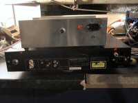
It's as discussed previously. To recap: the CD and CD chassis are connected to safety earth, CD has star ground point.
The PS is "disconnected" from safety earth via 8.2/22nF but the chassis is directly connected for safety and shielding. PS also has a star ground point.
The two stars are connected via the binding post on CD end and hard wired at PS end (soon to add isolated binding post, I didn't want to drill at 12.30am).
I hope it's clear now. It's not such a simple machine anymore! lol
Simon
rowemeister said:LOL would be interesting if that fell out. Looking good though.
Brent
It sure would be

Yeh, thanks mate, I'm really pleased with how it's working out.
Next is another transformer and I will separate digital and analogue (one tx. for each).
I did originally consider two sets of 8-way DINs, one for ana and one for dig, but now that the earth is separate 8 pins is going to go a long way! Three used so far: clock, divider, 5v board. The 5v will become two. Next will be two psus for the all-important servo I think. That's only 6 in total!
6h5c said:Hey Simon!
Nice pictures, looks very neat. Nice connector job! I guess i'm falling behind, since my players still use the internal PSU 😀. Maybe i'm going to make one with tubes
Ray
Thanks Ray. The neatness is questionable in places, nothing like your immaculate work.
Well, you may not have an external psu, but I do not have your excellent output stage built yet. It's pricey to make using only the best parts but I will get onto it as soon as time and money become available! I of course heard it in Brent's and I want!
Simon
Ray - why does your passive filter + FET output stage need a coupling cap on the end? Forgive my ignorance!
Also, I have four HA5033 buffers to hand (same as OPA633... I think) they only generate about 15mV of offset.
I'm wondering if I could attach these to the end of some passive filter.
HA5033
Also, I have four HA5033 buffers to hand (same as OPA633... I think) they only generate about 15mV of offset.
I'm wondering if I could attach these to the end of some passive filter.
HA5033
Glenn2 said:Ray - why does your passive filter + FET output stage need a coupling cap on the end? Forgive my ignorance!
Off the top of my head I think there is 7V dc on the output.
If people can't remember mine has the BG ac types fitted.
An externally hosted image should be here but it was not working when we last tested it.
Brent
SimontY said:Thanks Ray. The neatness is questionable in places, nothing like your immaculate work.
Simon
Thanks Simon, i'm honoured...😎
Glenn2 said:Ray - why does your passive filter + FET output stage need a coupling cap on the end? Forgive my ignorance!
Also, I have four HA5033 buffers to hand (same as OPA633... I think) they only generate about 15mV of offset.
I'm wondering if I could attach these to the end of some passive filter.
Brent is right, the output stage is single-ended and there's an offset present on the emitter of the last transistor (or FET). So decoupling (with a good cap obviously) is mandatory. Personally I wouldn't use an integrated buffer. The discrete output stage is by far less complicated compared to the internals of the 5033. I like to keep things simple, less is better. Besides, you don't need the extra speed and slew-rate of a video amp after a passive filter network. The figures in the datasheet like distortion and PSRR are not very impressive. But it won't hurt to try, I never did any experiments with these things and maybe it sounds quite good?
Be aware that the 15mV offset figure only indicates the offset generated by the device itself. For example if you offer 1,000V DC at the input you'll get 1,015V at the output 😀. You still have to get rid of the DC offset generated by the DAC.
Regards,
Ray
- Home
- Source & Line
- Digital Source
- Marantz CD63 & CD67 mods list