Re: Re: Re: Re: Servo Clock Mod
Thanks Dave and Brent.... I hear you guys... investing in a good clock seems to be fully worthwhile.... I'll look into both the Superclock and Hagclock (and Tent XO + PFM Flea). One of the downsides of being so far away is even at Ebay prices and once shipping to NZ is added, at the current NZ$ to UKP conversion rate... the price of a dedicated clock for DIY projects becomes a real killer!! But I'm begining to think that it's wothwhile.
Brent, your comment about a 5PPM crystal coming midway between an Audiocom replacement has really got me excited. 😀 As you probably recall from my very first post, I currently have a 5PPM crystal waiting to be dropped in (I actually tried it...but couldn't get the CD63 to work due to other problems). I'll put this low PPM crystal in again this weekend until I get a dedicated clock. Hope it works
Brent, when you replace the stock crystal to a 5PPM one, do you change the CD02 and CD03 capacitor values?
I had my custom clock crystal's circuit conditions specified to 18pF (parallel resonance mode). Would this mean I'd have to alter CD02 (10pF) and CD03(10pF) to something like CD02 (10pF), CD03 (5pF) + ~3pF from transmission line capacitance to ensure the clock will keep to 16.9344 MHz? 😕
If I get the 5PPM crystal working, I'll report on the difference between my baseline setup (which is the Acoustica clock hack http://www.acoustica.org.uk) and only changing the stock crystal to a 5ppm crystal. May be useful for those of you who don't intend to get a dedicated clock, but want to take the stock setup as far as it could go 🙂
Cheers,
Champi
Gooch said:
Champi
Checkout this clock card hagclock This is what I have it won't cost arm & leg I felt the same way you do that's why I never bought one years ago. Jim is a great guy and ships world wide. I even have some left over parts from building mine I could send you if that helps.
Regards,
Dave
rowemeister said:
Personally I would always got for a good clock! In the UK fitting a clock (at ebay prices) you will get your money back when selling the cdp. Also you would be able to use it in another player.
For me I have moddified mine so much I would have to spend a lot of money on a player to better it so ill probs keep it for ever lol.
Also make sure the clock will happily run 2 or more ics. I checked with Audiocom and they told me it would.
Also I tried to get the servo clock mod to work running off a crystal and its a no go, it can be done but there will be more work involved and not really any benefit.
I fit 5ppm crystals to players I mod where im not fitting super clock and they do improve the audio. I would say its half way between standard 50ppm crystal and audiocom clock.
Can you not get a Audiocom clock on ebay from UK.
http://cgi.ebay.co.uk/AUDIOCOM-SUPE...QitemZ9728848303QQcategoryZ3272QQcmdZViewItem
Brent
Thanks Dave and Brent.... I hear you guys... investing in a good clock seems to be fully worthwhile.... I'll look into both the Superclock and Hagclock (and Tent XO + PFM Flea). One of the downsides of being so far away is even at Ebay prices and once shipping to NZ is added, at the current NZ$ to UKP conversion rate... the price of a dedicated clock for DIY projects becomes a real killer!!
But I'm begining to think that it's wothwhile.Brent, your comment about a 5PPM crystal coming midway between an Audiocom replacement has really got me excited. 😀 As you probably recall from my very first post, I currently have a 5PPM crystal waiting to be dropped in (I actually tried it...but couldn't get the CD63 to work due to other problems). I'll put this low PPM crystal in again this weekend until I get a dedicated clock. Hope it works
Brent, when you replace the stock crystal to a 5PPM one, do you change the CD02 and CD03 capacitor values?
I had my custom clock crystal's circuit conditions specified to 18pF (parallel resonance mode). Would this mean I'd have to alter CD02 (10pF) and CD03(10pF) to something like CD02 (10pF), CD03 (5pF) + ~3pF from transmission line capacitance to ensure the clock will keep to 16.9344 MHz? 😕
If I get the 5PPM crystal working, I'll report on the difference between my baseline setup (which is the Acoustica clock hack http://www.acoustica.org.uk) and only changing the stock crystal to a 5ppm crystal. May be useful for those of you who don't intend to get a dedicated clock, but want to take the stock setup as far as it could go 🙂
Cheers,
Champi
Re: Re: Re: Re: Re: Servo Clock Mod
I changed cd02 and cd03 to same value silver mica.
Not sure on capacitance value change, try it with standard caps in first
Brent
pantera6 said:
Thanks Dave and Brent.... I hear you guys... investing in a good clock seems to be fully worthwhile.... I'll look into both the Superclock and Hagclock (and Tent XO + PFM Flea). One of the downsides of being so far away is even at Ebay prices and once shipping to NZ is added, at the current NZ$ to UKP conversion rate... the price of a dedicated clock for DIY projects becomes a real killer!!
Brent, your comment about a 5PPM crystal coming midway between an Audiocom replacement has really got me excited. 😀 As you probably recall from my very first post, I currently have a 5PPM crystal waiting to be dropped in (I actually tried it...but couldn't get the CD63 to work due to other problems). I'll put this low PPM crystal in again this weekend until I get a dedicated clock. Hope it works
Brent, when you replace the stock crystal to a 5PPM one, do you change the CD02 and CD03 capacitor values?
I had my custom clock crystal's circuit conditions specified to 18pF (parallel resonance mode). Would this mean I'd have to alter CD02 (10pF) and CD03(10pF) to something like CD02 (10pF), CD03 (5pF) + ~3pF from transmission line capacitance to ensure the clock will keep to 16.9344 MHz? 😕
If I get the 5PPM crystal working, I'll report on the difference between my baseline setup (which is the Acoustica clock hack http://www.acoustica.org.uk) and only changing the stock crystal to a 5ppm crystal. May be useful for those of you who don't intend to get a dedicated clock, but want to take the stock setup as far as it could go 🙂
Cheers,
Champi
I changed cd02 and cd03 to same value silver mica.
Not sure on capacitance value change, try it with standard caps in first
Brent
Re: Re: Re: Re: Re: Servo Clock Mod
Stock setup? lol. Not really stock is it? 😉
I'd be interested to hear your findings.
Simon
pantera6 said:May be useful for those of you who don't intend to get a dedicated clock, but want to take the stock setup as far as it could go 🙂
Stock setup? lol. Not really stock is it? 😉
I'd be interested to hear your findings.
Simon
disco said:
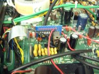
Maybe this small board can be of help. It consists of a 7805 reg with two accompanying caps (.33 and .1uF), a SMB jack and the 74LS74.
The board can be fitted in the hole above C142 (on the left side).
As mentioned in an earlier post by Allen, the reg gets its ground from star ground. Maybe someone can scrutinize the connections, as there was a small dispute about wiring.
Regards, Jaap
Hi Jaap
Nice diagram. I can see a few errors! the reg gnd and star is not connected to gnd and no output shown.
I have edited it for you to see and added a X7R cap across pin 7 and 14.
Everything else appears spot on mate.
P.S The divider circuit is not required for the servo on a 67 as the servo and decoder are in one chip and its divided internally.
Brent
Attachments
rowemeister said:Hi Jaap
Nice diagram. I can see a few errors! the reg gnd and star is not connected to gnd and no output shown.
I have edited it for you to see and added a X7R cap across pin 7 and 14.
Everything else appears spot on mate.
P.S The divider circuit is not required for the servo on a 67 as the servo and decoder are in one chip and its divided internally.
Brent
Thanks for the coop Brent. 🙂
Will implement the X7R cap (22nF?) and ground connection.
For output I thought of a 47 ohm direct from pin 5 on the PCB through the hole of former X101, to pin 19 of the TDA1301.
Or would this form a nice HF antenna?

Regards, Jaap
Jaap.
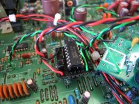
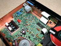
Use the right hole from R126 as for the hot wire and the middle hole of X101 for gnd. It's marginal closer to the servo. My 47R is placed on my vero. See pic.
I know, it's painted black, it seems to match the eye better that the brown pertinax. It's kind of stealth
 😀
😀
Use the right hole from R126 as for the hot wire and the middle hole of X101 for gnd. It's marginal closer to the servo. My 47R is placed on my vero. See pic.
I know, it's painted black, it seems to match the eye better that the brown pertinax. It's kind of stealth
😀Attachments
avr300 said:I know, it's painted black, it seems to match the eye better that the brown pertinax. It's kind of stealth
Looks good avr, how's she sounding now? Best cd player you've heard yet?
Si
disco said:
Thanks for the coop Brent. 🙂
Will implement the X7R cap (22nF?) and ground connection.
For output I thought of a 47 ohm direct from pin 5 on the PCB through the hole of former X101, to pin 19 of the TDA1301.
Or would this form a nice HF antenna?
Regards, Jaap
No probs mate.
I direct coupled mine with no resistor, and as avr300 said use the hole from the 1M resistor.
Brent
avr300 said:Jaap.
Use the right hole from R126 as for the hot wire and the middle hole of X101 for gnd. It's marginal closer to the servo. My 47R is placed on my vero. See pic.
I know, it's painted black, it seems to match the eye better that the brown pertinax. It's kind of stealth
Thats why I used a blue pcb, black looks good.
Brent
Attachments
avr300 said:Jaap.
Use the right hole from R126 as for the hot wire and the middle hole of X101 for gnd. It's marginal closer to the servo. My 47R is placed on my vero. See pic.
I know, it's painted black, it seems to match the eye better that the brown pertinax. It's kind of stealth
Thanks for the help.
Black is quite fashionable 😀
Jaap
Attachments
disco said:
Thanks for the help.
Black is quite fashionable 😀
Jaap
Very nice disco.
Brent
You boy's have to learn to colour co-ordinate.
otherwise the better half's will never accept it
allan
otherwise the better half's will never accept it
allan
SimontY said:
Looks good avr, how's she sounding now? Best cd player you've heard yet?
Si
Indeed very impressing. It really gives body to the music.
Next mod is a couple of superegs for the opamps. Anyone, comments on ALW' SR ? http://www.alw.audio.dsl.pipex.com/
Is there a circuit board available, like the Flea board?
awpagan said:You boy's have to learn to colour co-ordinate.
otherwise the better half's will never accept it
allan
Correct - green and black - military colours. Brent - your's navy !
Actually she quite likes it. Both the look and the sound.
avr300 said:
Correct - green and black - military colours. Brent - your's navy !
Actually she quite likes it. Both the look and the sound.
It more a Royal blue lol
Brent
avr300 said:
Next mod is a couple of superegs for the opamps. Anyone, comments on ALW' SR ? http://www.alw.audio.dsl.pipex.com/
Is there a circuit board available, like the Flea board?
I'm doing the same at the moment. My opamps are powered by two LM317 based regs, so I hope ALWSR will improve things. I'm going to produce the pcb in local pcb house.
It would be really interesting to hear other's experience about ALWSR.
So - done deal.
But why do I have a DC offset, 25mV (spot on, each channel) allready present on pin1 of the opamp?
I have to say that the DC offset allready was there, before I did the resistor makeover. Before it was 18mV and 50mV, now it's similar, L and R (so my job is ok ).
).
But why do I have a DC offset, 25mV (spot on, each channel) allready present on pin1 of the opamp?
I have to say that the DC offset allready was there, before I did the resistor makeover. Before it was 18mV and 50mV, now it's similar, L and R (so my job is ok
).
disco said:
Jaap,
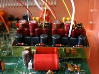
Sorry to sound daft, but the pic you posted of the circuit board close to the RCA outputs .... is that your passive filter + FET output stage??
- Home
- Source & Line
- Digital Source
- Marantz CD63 & CD67 mods list