Hi!
I'm having a strange issue with a marantz CD-5400.
When I close the tray with a cd (or without cd) the spindle gives a short spin and stops again, another spin and stop again for about 5 times. I can see the laser coming on but the lens only goes up a tiny little bit once, even less the second time and than it stays down. I got frustrated after cleaning everything, touching up a whole bunch of broken joints without result and kind of lost it on the stand by button turning the player on and off a few times, at the end the player actually turned on, cd spun and started reading just fine. I turned it off again and checked the laser without a cd, it now goes up and down just fine and can clearly read the cd without any problem. I unplugged the player, plugged it back in connected to my amp to listen, well, same issue again. I kept turning it on and off, sometimes it works fine, sometimes it has the issue. I seems to be an intermittent loss of focus gain but I don't really see how this is related to how the player turns on 😕.
I once had a similar-ish problem on a Sony Discman (the original version that used a KSS110 pickup) and the lens assembly was sticking on its spigot bearing.
It was a real one off fault but it would still be worth checking the lens is free.
It was a real one off fault but it would still be worth checking the lens is free.
Hi Mooly, always present 🙂,
Actually I tried replacing the laser assembly with a generic one and now the problem is even worse, sometimes I see a tiny movement from the lens (probably corresponding to when the original one achieved focus) and sometimes there is no movement at all. So same symptoms but worse. It's definitely a servo issue, or a power supply, or even a CPU issue...
Actually I tried replacing the laser assembly with a generic one and now the problem is even worse, sometimes I see a tiny movement from the lens (probably corresponding to when the original one achieved focus) and sometimes there is no movement at all. So same symptoms but worse. It's definitely a servo issue, or a power supply, or even a CPU issue...
No easy answers to that one then 🙁
All you can do is work back from the focus coils to the drive amp and see if anything seems amiss. Supplies of course and also look at the focus drive waveform input to the chip/drive amp.
Try and compare working and not working states if possible.
All you can do is work back from the focus coils to the drive amp and see if anything seems amiss. Supplies of course and also look at the focus drive waveform input to the chip/drive amp.
Try and compare working and not working states if possible.
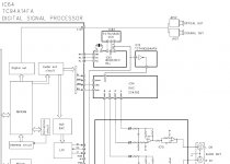
The problem seems to be before the drive amp because the signal arriving at the drive amp isn't what it's supposed to be when in not working state. The waveform seems to be a positive pulse (in any state) changing in voltage when the lens goes up or down . In the not working state the pulses are still visible but when the laser tries to focus the voltage doesn't change or at least not enough to drive the focus coils, also the signal gets "blurry", I don't really know how to describe it but it looks like there is some high oscillation riding on the waveform whenever it it tries to move the lens. My issue is that this signal comes straight from the digital signal processor IC and from there I don't really know where to look. There aren't any voltage except for supply rails on the schematics and I not actually sure I can measure on the ic which is on the back of the board with the player turned on.
Last edited:
I suppose if the continuity from the SYSCON chip to the drive amp is OK then there is little else. I can see on the circuit just a 100 ohm and a 47? pf cap (do they mean 470pF or a 47 and a zero as in 47 pF).
Might be worth isolating that 100 ohm to make sure the drive amp chip isn't the one pulling it astray.
Might be worth isolating that 100 ohm to make sure the drive amp chip isn't the one pulling it astray.
I disconnected the 100ohm resistor and the waveform stays intermittent, I did by doing so however manage, once connected again, to get the generic laser assembly to focus correctly. Now I poked around some with the oscilloscope and on pin 46 (X1) of IC64 (syscon chip) indicated on the block diagram as the input of the clock generator, the oscillations get bigger in amplitude when in not working state and voltage wise the it is lower in not working state (2.77v against 3.5V in working state).
The working state signal going in to pin 46 is a nice sine wave at about 17Mhz like it should but in not working state both positive and negative peaks have a strange dent and also frequency drops to about 12Mhz, I checked the output of the crystal oscillator itself and that stays solid so I'm guessing something is wrong with either IC61 or IC62 (both supply rails are good in both working and not working situations).
Does it have a flat cable between the transport n main board?
If there us, check if any of the pins are damaged or off alignment
If there us, check if any of the pins are damaged or off alignment
It does have flat cable but but once the player is in either on of the two states unplugging or moving this cable doesn't change anything to the issue it stays in the same state, only turning it on and off multiple times can get it from one to the other.
It is never the big chip 😉 but there really is little else in this player.
Could it be any form of contamination anywhere? If the player has an unknown history then you never know. Might be worth a wash of the board.
Could it be any form of contamination anywhere? If the player has an unknown history then you never know. Might be worth a wash of the board.
IC 61 and 62 aren't big chips, one is a BU2630, seems to be a pll frequency synthesizer and 74ls628 (still available at mouser), a voltage controlled oscillator.
The insides look really clean, just like the outside.
I just found out that when in working state, if I short out the 50v 1µF going from pin 13 of IC 62 (the oscillator) to ground I get the exact same waveform as when it's in not working state. Although I don't really see a cap having an intermittent problem like this I replaced it with a wima film cap but as expected, no difference. I think I'll go ahead and order a new sl628 oscillator and see where that gets us.
Did you double check all the supply voltages and filtering capacitors? I'm just saying, as you noticed the problem being intermittent when switching on/off, I didn't see you mention that it happened intermittently while the player is still on?... maybe there's a voltage regulator not working as expected, not providing correct supply to these oscillators? Did you try to isolate the source of the signal from the rest of the circuit, to see if the signal stays consistent or gets different intermittently? I mean, imagine the drive amp is defective and sometimes somehow "shorts" its input resistance, then the output signal from the previous oscillator circuit would at least be influenced. This is a weird problem and hard to trace, it seems.
Indeed once the player is on it is either working or not working, it only changes if the player is turned off and on again (sometimes only after 3 cycles, sometimes after 30). The supply rails are all there and have the correct voltages even when it doesn't work correctly. It sometimes looks like something is charging/discharging and by doing so it changes the shape (kind of looks like clipping) and frequency of the oscillator. I removed the drive amp out of the equation by disconnecting R132 and nothing changed. The only other element I could try to disconnect from the output of the oscillator is the input of IC12 (Toshiba TC74ACT04FN).
After reading through, I'd take the same conclusions as you, one of the two chips might be defective. But, I don't have the SM at hands, as you're saying VCOs and PLL, I suppose they have some passive components around them? Might very well be some of these components going bad, making the PLL loose lock, for example, or the VCO to alter what should stay the same... maybe before changing these chips, change all surrounding passive components first?
The manual is available at hifiengine 🙂
Yes there are some passive components, not a whole lot, I checked the 3 electrolytics, replaced them one by one and than put them back because that didn't change anything. Could a ceramic cap get intermittent like this ?
I'll check the rest tomorrow. Anyway IC12 and IC 62 are available at mouser for almost nothing, it's worth trying. The only thing that worries me is if the issue is the BU2630 because that seems to be obsolete.
Hello again
I replaced Both IC 62 and IC12 without any result. I also changed C611 and R611, still nothing. Now I did notice something I did not before, when things aren't working correctly I have 0V on pin 13 of IC62 against 1.9V when working (that's also why when it turns on and gets back to working state it looks like a cap is charging, that would be C609 and C615 respectively 100µf and 1µF) which according to the datasheet is the phase comparator output. That only leaves IC 61 🙁.
I replaced Both IC 62 and IC12 without any result. I also changed C611 and R611, still nothing. Now I did notice something I did not before, when things aren't working correctly I have 0V on pin 13 of IC62 against 1.9V when working (that's also why when it turns on and gets back to working state it looks like a cap is charging, that would be C609 and C615 respectively 100µf and 1µF) which according to the datasheet is the phase comparator output. That only leaves IC 61 🙁.
Last edited:
Oh dear 🙁
I know sometimes you reach a point where you have to try the chip if only to eliminate it it. I wouldn't bet on it but perhaps you might get lucky if you can score a replacement.
I know sometimes you reach a point where you have to try the chip if only to eliminate it it. I wouldn't bet on it but perhaps you might get lucky if you can score a replacement.
There are quite a few on ebay, it hasn't been obsolete for that long so I hope there aren't to many fakes out there. There are only very little components around these chips and I don't see any that could be a problem. Can any one help me find out what PLL SCl and SDA mean going or coming to/from IC71 are ? The datasheet for IC61 lists these three pins as chip enable/ clock signal and serial data.
Serial clock and serial data sound like an I2C control bus which is just a standard two wire system of allowing lots of chips to communicate to and fro. You have one control chip (master IC71) that can address all the others as and when needed (slaves).
All that can done with data lines like these is just to verify the signal looks clean and of correct amplitude. Usually 'if its there' it is correct.
IC61 appears to be used to derive the master clock for the DAC according to the block diagram.
All that can done with data lines like these is just to verify the signal looks clean and of correct amplitude. Usually 'if its there' it is correct.
IC61 appears to be used to derive the master clock for the DAC according to the block diagram.
Attachments

- Home
- Source & Line
- Digital Source
- Marantz CD-5400 start up issue