LM4562 is allrigt
For IV i prefer THS 4032 though
In my headphone amp it's more detailed then the NE5532, still a bit hard but it hasn't had time to burn in yet.
IV?
There's an interesting article about using the 317/337's here it's worth clicking back through to parts 1, 2 & 3 to understand the final result. I must say that I haven't tried these yet but will be doing so.
I do recommend using a good size heatsink for whatever regulator you decide for the 7220, I ran with a single TO heatsink and it shut itself down a few times before I realised what was happening (this may have led to the untimely demise of my filter!). If you have a large heatsink available in the player then you could tie the regulator to that but isolate it as the LM317 case is vOUT! In my case there was a 7805 or similar attached to that heatsink and I essentially grounded the 317 (that may also have contributed!).
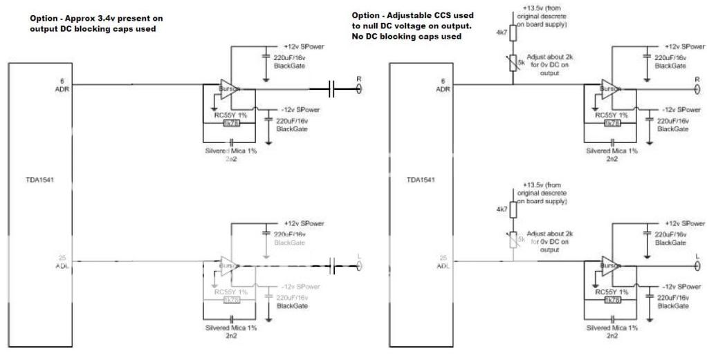
I tried NE5534, OPA227, OPA134 as well as the original LM833 and in the end, to be honest, I couldn't tell a big difference, if pushed I'd say the 134 was a little harsh but who knows, it could be the implementation and the fact the OPA's are single. They were all configured as i/v with the same value resistor and cap and all went straight to the RCA's via another cap to block the dc (no additional gain).
I did find that the physical implementation of the opamps made a big difference, even soldered straight onto a board (rather than via a socket) gave a noticeable improvement in my case, especially with the newer, faster opamps. You could take a feed straight from the DAC, build a dedicated board per variety of opamp then swap them quickly. You can then add a different stage altogether later without too much trouble.
I do recommend using a good size heatsink for whatever regulator you decide for the 7220, I ran with a single TO heatsink and it shut itself down a few times before I realised what was happening (this may have led to the untimely demise of my filter!). If you have a large heatsink available in the player then you could tie the regulator to that but isolate it as the LM317 case is vOUT! In my case there was a 7805 or similar attached to that heatsink and I essentially grounded the 317 (that may also have contributed!).
I tried NE5534, OPA227, OPA134 as well as the original LM833 and in the end, to be honest, I couldn't tell a big difference, if pushed I'd say the 134 was a little harsh but who knows, it could be the implementation and the fact the OPA's are single. They were all configured as i/v with the same value resistor and cap and all went straight to the RCA's via another cap to block the dc (no additional gain).
I did find that the physical implementation of the opamps made a big difference, even soldered straight onto a board (rather than via a socket) gave a noticeable improvement in my case, especially with the newer, faster opamps. You could take a feed straight from the DAC, build a dedicated board per variety of opamp then swap them quickly. You can then add a different stage altogether later without too much trouble.
There's an interesting article about using the 317/337's here it's worth clicking back through to parts 1, 2 & 3 to understand the final result. I must say that I haven't tried these yet but will be doing so.
I do recommend using a good size heatsink for whatever regulator you decide for the 7220, I ran with a single TO heatsink and it shut itself down a few times before I realised what was happening (this may have led to the untimely demise of my filter!). If you have a large heatsink available in the player then you could tie the regulator to that but isolate it as the LM317 case is vOUT! In my case there was a 7805 or similar attached to that heatsink and I essentially grounded the 317 (that may also have contributed!).
I tried NE5534, OPA227, OPA134 as well as the original LM833 and in the end, to be honest, I couldn't tell a big difference, if pushed I'd say the 134 was a little harsh but who knows, it could be the implementation and the fact the OPA's are single. They were all configured as i/v with the same value resistor and cap and all went straight to the RCA's via another cap to block the dc (no additional gain).
I did find that the physical implementation of the opamps made a big difference, even soldered straight onto a board (rather than via a socket) gave a noticeable improvement in my case, especially with the newer, faster opamps. You could take a feed straight from the DAC, build a dedicated board per variety of opamp then swap them quickly. You can then add a different stage altogether later without too much trouble.
I'll read that article tomorrow(save it to my pc for future reference).
Reading up as much as I can, so thanks!
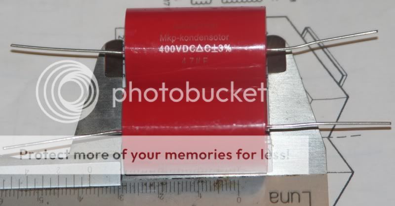
I'll wait until I can order the LM4562's then. Will take the signal directly from opamps, via 4,7uF/400V MKP, to outputs. You're supposed to take the signal from the first two opamps(lifting a capacitor and bypassing the rest w the MKP?) right?
I shouldn't write more today, tired and the the lights are on but nobody's home "upstairs" so to speak 😀
Last edited:
Mayday, look at the last page of that clocking doc. It shows a single opamp as I/V. Using an LM4562, LME47920 or LME 47860 will produce enough drive into most amps. I use 2n2 in parallel with 1k78 as the filter and a decent 4.7th output cap. Did this in a pals CD65se last night with excellent results.
One thing I did notice that I should have pointed out previously is that you may start to run into issues with output muting with very large caps 🙂 The easiest answer is to turn the CD on 1st and off last ;-)
One thing I did notice that I should have pointed out previously is that you may start to run into issues with output muting with very large caps 🙂 The easiest answer is to turn the CD on 1st and off last ;-)
Mayday, look at the last page of that clocking doc. It shows a single opamp as I/V. Using an LM4562, LME47920 or LME 47860 will produce enough drive into most amps. I use 2n2 in parallel with 1k78 as the filter and a decent 4.7th output cap. Did this in a pals CD65se last night with excellent results.
One thing I did notice that I should have pointed out previously is that you may start to run into issues with output muting with very large caps 🙂 The easiest answer is to turn the CD on 1st and off last ;-)
Will read it again, alot of info now...trying to learn eagle to 🙄
By filter you mean between pos and gnd on the rca's right(zobel?)?
I allways switch the stereo on and off in a certain order, so that shouldn't be a problem.
I've put together a list of mods, and order to do them(not complete yet). Will take them time to listen between mods:
1. Fix the cd-clamp DONE
2. Decouple TDA1541 DONE
3. Put in the 22000uF TSU DONE
4. Put 2000uf low esr in parallell w each of the 3 other caps before regs
5. Replace the caps after regs w 470uF ZLH
6. Put 470uF ZLH around opamps
7. Put the other ones UV101 recommended by the digital circuits
8. Bypass everything after first opamps to rca via 4,7uF MKP
9. Remove the pcb for variable out(is it just to disconnect all connectors and jank out?).
10. Dedicated PS to SAA7220
That's what I've gotten so far, after that there's clock, more dedicated PS etc 🙂
The fun never ends 😀
The filter form part of the feedback loop. Its not Zobel.
Ahh, I see.
It's a filter between two pins on the opamps. Between input and output pins.
Yes between output and non inverting ( - ) input 😉
In the case of LM4562:
Between pin1 and pin3 or pin5 and pin7, or both?
Looking at datasheet for LM4562.
Or am I missing the hole thing?
Anyway, I've got the time to get it right, haven't gotten my MKP's yet.
Trying not to rush 🙂
Not a CD50 or a CD60 but one in the middle! CD65SE!
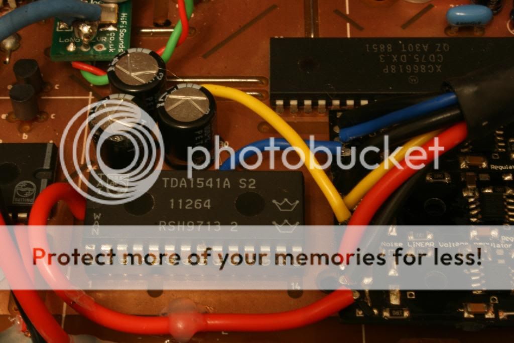
Just finished modding this for a pal. Lots of similar chips and all the same principles apply!
Too much done to list but there are 10 regs, a clock and complete re-cap to start ;-)
You can see why I keep to small regs and dont use any of the larger type. It would be impossible to get this many larger regs in!
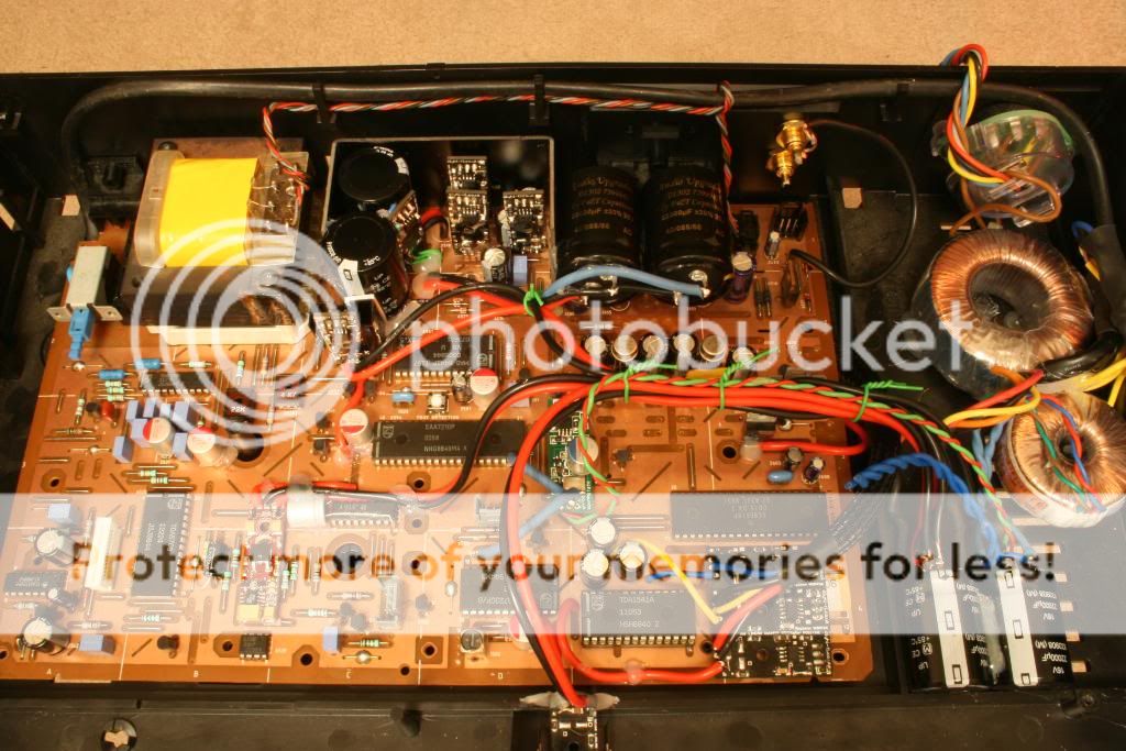


Started like this before the weekend!!!!
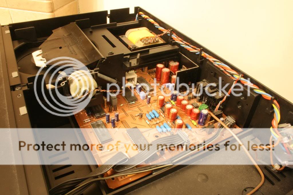
A bit of investigation and the service manual resulted in a plan!!!

Just running in at the mo 😉
Just finished modding this for a pal. Lots of similar chips and all the same principles apply!
Too much done to list but there are 10 regs, a clock and complete re-cap to start ;-)
You can see why I keep to small regs and dont use any of the larger type. It would be impossible to get this many larger regs in!
Started like this before the weekend!!!!
A bit of investigation and the service manual resulted in a plan!!!
Just running in at the mo 😉
Last edited:
.....and it sounds.... amazing ?
Double Crown..all those regs, three traff's, large lytics, re cap, clock etc etc ?
Lottery winner ?
What a lucky man he is.....blimey 😱
Double Crown..all those regs, three traff's, large lytics, re cap, clock etc etc ?
Lottery winner ?
What a lucky man he is.....blimey 😱
That's looking really nice UV101 !!
I bet it'll sound even nicer then it looks 🙂
How much £ do you think you spent?
I bet it'll sound even nicer then it looks 🙂
How much £ do you think you spent?
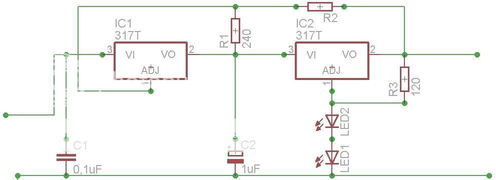
I'm starting to zero in on the TPR w 2 LED's in series on R4.
Was told this would give 5,25Vdc very low noise, 5,25v close enough to work(SAA7220 & clock, one for each)? If not, how do I lower V to 5,0V without adding noise? Specs for the LED's to be used should be?
Was told this would give 5,25Vdc very low noise, 5,25v close enough to work(SAA7220 & clock, one for each)? If not, how do I lower V to 5,0V without adding noise? Specs for the LED's to be used should be?
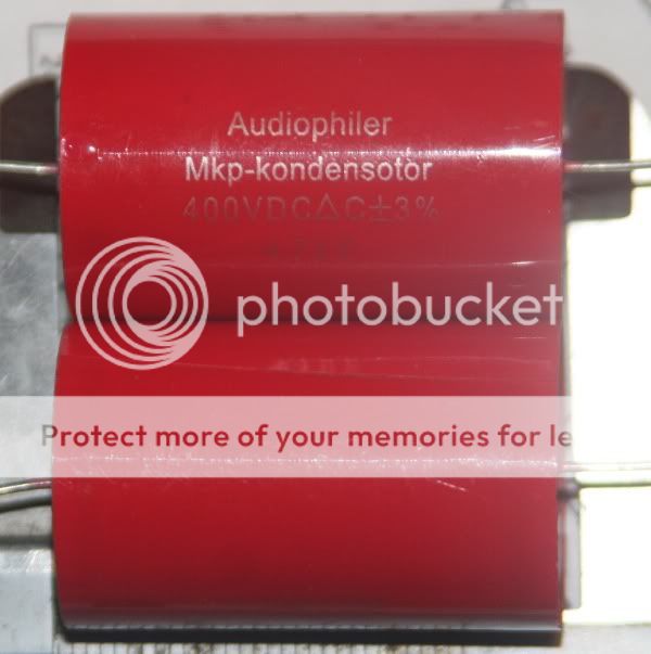
Got these today, how do they compare to ZLH(which I will get anyway, thanks to UV101):
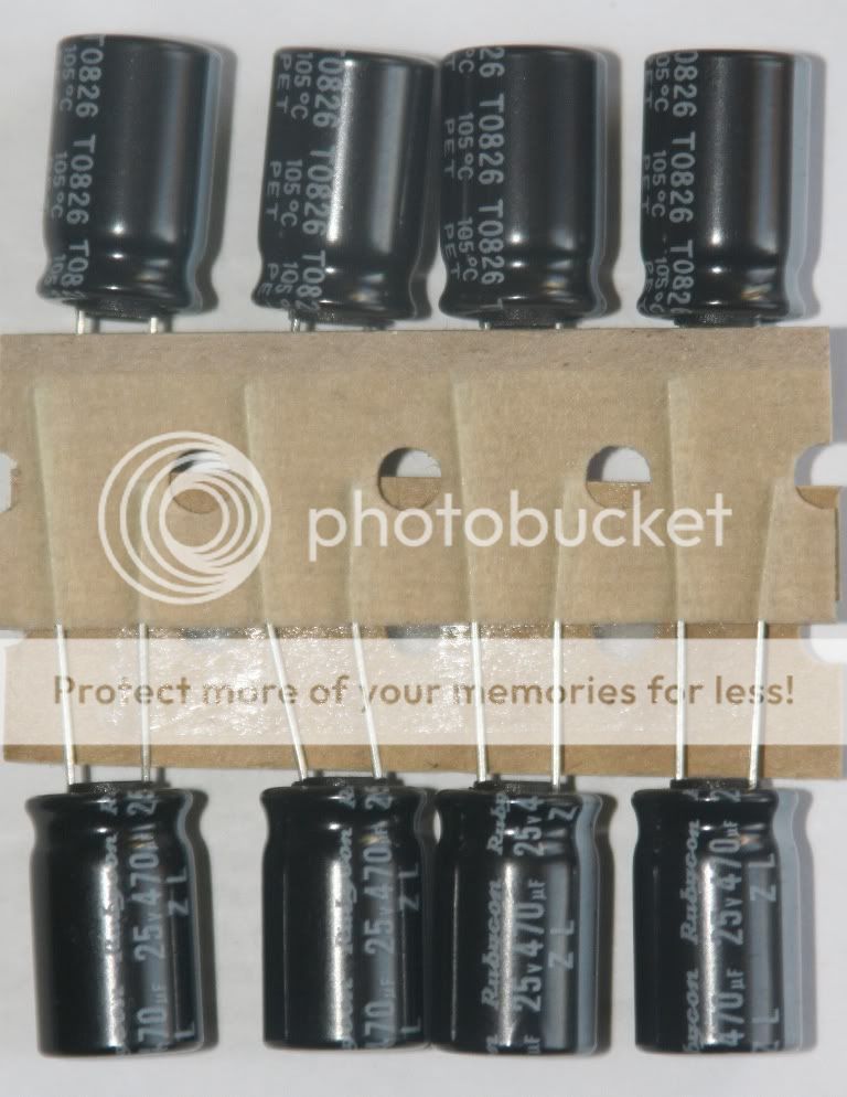
Also, can I parallell the 470 ZLH under the PCB or should I remove the originals(2704,2714,2708,2712)?
Also, can I parallell the 470 ZLH under the PCB or should I remove the originals(2704,2714,2708,2712)?
Last edited:
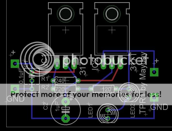
Tried to make a descent regulatorboard in eagle, don't mean to steal anything, the test on the board is only because I'll just have them made for me.
Any thoughts?
Any thoughts?
I'm trying to learn to use eagle, so I made a design from a schematic earlier posted in this topic.
J1 and J1 are to be connected by wire(making it a one-sided PCB)
An externally hosted image should be here but it was not working when we last tested it.
J1 and J1 are to be connected by wire(making it a one-sided PCB)
An externally hosted image should be here but it was not working when we last tested it.
.
I think I've asked but not sure I got an answer;
What kind of LED:s is best to use in this application?
Found rather cheap EI transformers 10VA 1x9Vdc(1200mA). 3 of these would easily fit when I remove the pcb for variable output. One for each of these: saa7220, 7310 and later a clock.
What kind of LED:s is best to use in this application?
Found rather cheap EI transformers 10VA 1x9Vdc(1200mA). 3 of these would easily fit when I remove the pcb for variable output. One for each of these: saa7220, 7310 and later a clock.
Last edited:
- Status
- Not open for further replies.
- Home
- Source & Line
- Digital Source
- Marantz CD-50 and CD-60, TDA1541, CDM4/19