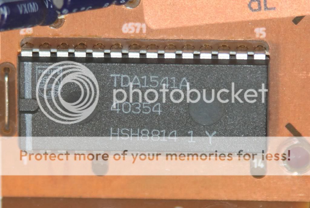
I didn't ground it for the TDA re clock ( 2 & 4 )
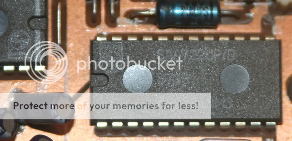
I did however ground it to the main board when I did the 7310 and 7220.
I did however ground it to the main board when I did the 7310 and 7220.
I didn't ground it for the TDA re clock ( 2 & 4 )
I did however ground it to the main board when I did the 7310 and 7220.
Any place that's better then others, avoiding loops etc(if that even occurs in this applikation)?
Tell you what....I'll have a look tomorrow and flag it up if that's OK.
That would be great, thanks 🙂
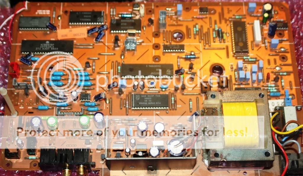
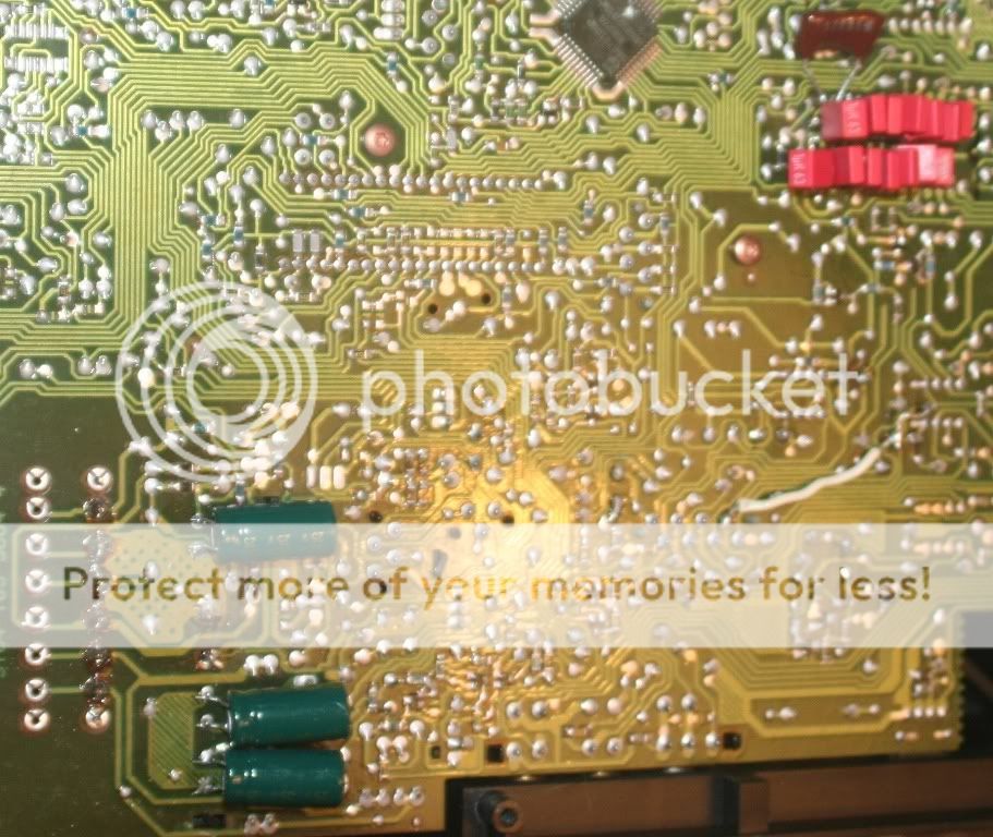
There's quite a few solder blobs on wire links on the top of the board, I attached the clock GND to one of these near the TDA and this works perfectly. I'm sure it's not 'optimal' but optimizing the grounds on these things, especially when you have more than one PSU, is not something I've attempted yet. It's on the (long) list!
Morning guys! Looks like you lasted later than I did last night 😉
Andrew, yep single burson opamp I/V straight to the output. Exactly what's on the last page of the doc that I partially wrote and partially compiled!! Lol there will be an argument that you need 2 stages as the 1st inverts the signal. Tbh, I used my ears and it was the best sounding tda set up I'd ever heard. I am going to play with a discrete I/V in the new year tho. It will also work with a normal opamp 😉
Clock gnd......I remember being told by Trichord research (the guys name escapes me at the moment) to only gnu at the clock end (not psu). This will avoid gnd loops. What I tend to do now, is pick up power and gnd from the psu, then use small coax for the clock out but only gnd at the clock end (so the braid is gnd, but not forming part of the return path). I cannot say if this makes anything sound any better, but it makes sense in my head!!!!
When you have done loads, and have many psu's gnds are a pain in the ****!!!! It's so easy to inadvertently introduce a hum inducing loop!!!!!!!
Thank's UV, will have to look for very thin coax-cable then 🙂
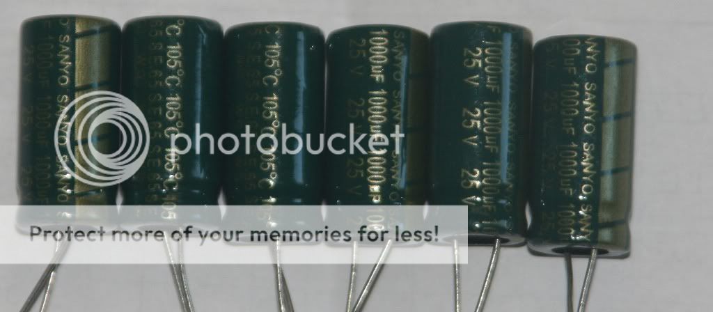
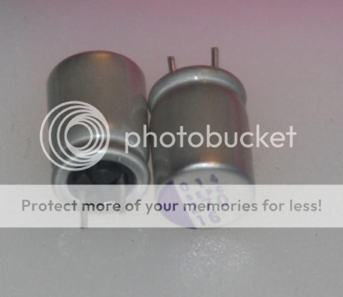
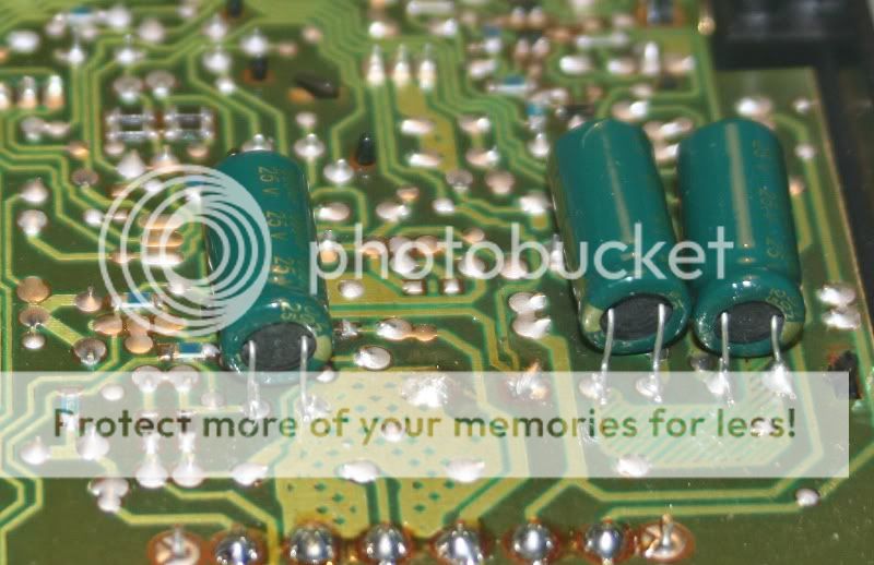
Got these today, was planning on putting one of each in parallell with the 3 yet unchanged elco's before the regs(the ones next to the 22000uF TSU)
Got these today, was planning on putting one of each in parallell with the 3 yet unchanged elco's before the regs(the ones next to the 22000uF TSU)
They'll be fine - no insulation needed.🙂
Thanks! Got some other stuff today too 😀
Marantz CD-75mkII working, Marantz CD-75mkII PCB and a bunch of tubes.
An externally hosted image should be here but it was not working when we last tested it.


The tubes I got are:
Tungsram UBC41 2pcs
Philips Import ECC86 2pcs
Philips Import ECC84 2pcs
Siemens PCF82 2pcs
Philips PCF82 2pcs
Miniwatt UF85 1pc
Philips Import UF85 1pc
Brimar DF91 2pcs
Triotron DAF96 2pcs
Miniwatt EF91 4pcs
Tungsram UBC41 2pcs
Philips Import ECC86 2pcs
Philips Import ECC84 2pcs
Siemens PCF82 2pcs
Philips PCF82 2pcs
Miniwatt UF85 1pc
Philips Import UF85 1pc
Brimar DF91 2pcs
Triotron DAF96 2pcs
Miniwatt EF91 4pcs

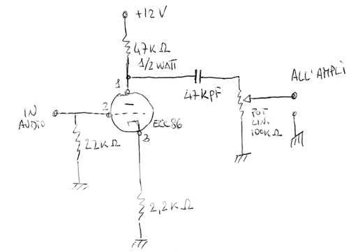
Hi Mayday, That 22K resistor looks kind of high to me. At least for a TDA1541. ??? If that is a I/V resistor it usually is less then 100 Ohms.... Unless I missed something? Dave😕
Hi Mayday, That 22K resistor looks kind of high to me. At least for a TDA1541. ??? If that is a I/V resistor it usually is less then 100 Ohms.... Unless I missed something? Dave😕
The schematic is actually from a pre-amp, was pointed to it for a place to start.
The Sanyo oscon sepc 270uF/16V I ordered a while ago are now waiting at the postoffice.
My fiance will collect them later today but I won't do any solderwork until my fever is gone.
My fiance will collect them later today but I won't do any solderwork until my fever is gone.


- Status
- Not open for further replies.
- Home
- Source & Line
- Digital Source
- Marantz CD-50 and CD-60, TDA1541, CDM4/19