I want to duplicate the Marantz 7C tone stacks in my 7C replica build. I purchased what I thought would work for the bass tone rotary switch based on my interpretation of the schematic but in looking at photos of a disassembled 7C bass rotary switch and the level of complexity of the one Marantz used, I am wondering if what I want to use is capable.
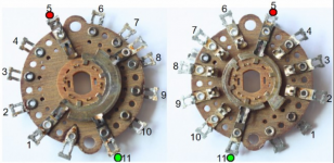
The Marantz switch is a dual deck 11 position with each deck having two poles. Each deck is dual sided with two different types of center conducting pad traces. The switch also has a termination disc further out from the two decks to attach the capacitors and resistors.
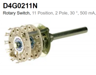
I purchased dual deck 11 position single pole switches and I can't see why it wouldn't work. I will be adding a terminal plate via long standoffs as Marantz used on their switches
Looking for someone to look at the attached schematic of the switch from the Marantz 7C schematic and photo of the switch I'm going to try and use and tell me if my simple 11 position dual deck rotary can perform the necessary switching?
The Marantz switch is a dual deck 11 position with each deck having two poles. Each deck is dual sided with two different types of center conducting pad traces. The switch also has a termination disc further out from the two decks to attach the capacitors and resistors.
I purchased dual deck 11 position single pole switches and I can't see why it wouldn't work. I will be adding a terminal plate via long standoffs as Marantz used on their switches
Looking for someone to look at the attached schematic of the switch from the Marantz 7C schematic and photo of the switch I'm going to try and use and tell me if my simple 11 position dual deck rotary can perform the necessary switching?
Attachments
I'm glad to hear others here also feel it should work.
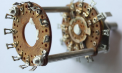
Thought I'd show a couple of photos showing the complexity of the C7 switch and then will ask an obvious question. What would have been their motivation behind using something that would have to be a custom engineered switch and that would cost them much more per switch compared to standard off the shelf offerings at the time? If a simple standard rotary design does the job, no company that I've ever heard of would add cost to a design unless it was required to perform the function or somehow saved labor $ somewhere else in an amount greater than the added expense.
Thought I'd show a couple of photos showing the complexity of the C7 switch and then will ask an obvious question. What would have been their motivation behind using something that would have to be a custom engineered switch and that would cost them much more per switch compared to standard off the shelf offerings at the time? If a simple standard rotary design does the job, no company that I've ever heard of would add cost to a design unless it was required to perform the function or somehow saved labor $ somewhere else in an amount greater than the added expense.
Attachments
Last edited:
Such switches were custom made for audio or other mfrs back then. Still are, since there are a vast number
of options, and no manufacturer or distributor would want to stock them all. The switches were made with
all standard parts coming right out of stock, just custom assembled to order, to make the configuration wanted.
of options, and no manufacturer or distributor would want to stock them all. The switches were made with
all standard parts coming right out of stock, just custom assembled to order, to make the configuration wanted.
Last edited:
That makes sense to me. Most likely was not much of an increase in cost but potentially allowed a big reduction in wiring and component connections which would equate to big savings in labor. I tried studying the circuit pathways that resulted using their switch versus the simple one I want to use and after getting cross eyed, I decided it would be too challenging. I'll wire it as I interpret the schematic and hopefully will end up with the same tone stack switching.
Only difference is the way all the RC connections are made to the preceding plate.
You'll have lots of wiring to do.
A soldered connection is better than the sliding switch contact anyway.
You'll have lots of wiring to do.
A soldered connection is better than the sliding switch contact anyway.
Last edited:
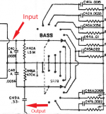
I'm finally ready to start soldering the RC components to my bass and treble rotary selectors on my Marantz 7C build but have a question for anyone having expertise in RC filters for tone amps. I want to make sure I start attaching the filters in the correct order so that rotating clockwise, it increases treble and bass rotary increases bass.
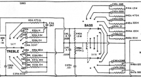
In looking at the attached image of the two ganged bass rotary with parallel RC filters and single ganged treble rotary with series RC filters, I need to know which direction of rotation one would turn it (CC, CCW) to increase treble and increase bass if image was of the front of the selector with knob facing you.
Not certain if image is of front or back of selector.
Attachments
That's just a schematic, and is not intended to be a physical representation of the rotary switch.
We always draw CW rotation of the control knob as increasing the volume or amount of boost.
Use a DVM to trace connections between the input and output of the switch to map it electrically.
You may have received a diagram with the switch when you bought it.
We always draw CW rotation of the control knob as increasing the volume or amount of boost.
Use a DVM to trace connections between the input and output of the switch to map it electrically.
You may have received a diagram with the switch when you bought it.
Last edited:
Hi rayma, I'm constructing the rotary switches from scratch and do not have anything to map.
Another possible way to ask this is when looking at the RC values in the bass control schematic representation, do you know which end of the range of RC values listed in the schematic would be allowing more bass to pass versus less?
Another possible way to ask this is when looking at the RC values in the bass control schematic representation, do you know which end of the range of RC values listed in the schematic would be allowing more bass to pass versus less?
Can you post some close, clear photos of the switch?
Especially the front side and the back side.
This is very complex to construct, are you sure you can do it correctly?
Especially the front side and the back side.
This is very complex to construct, are you sure you can do it correctly?
Attachments
Last edited:
Back at the beginning of this thread I posted that I would be attempting to go with a basic 2 deck, single pole, 11 position switch for the bass rotary. See link below.
https://www.diyaudio.com/forums/tubes-valves/375990-marantz-7c-build-tone-rotary-switch.html#post6759215
And, would be doing additional wiring to alleviate having to use the more complex switch Marantz used for the task. It seemed more than doable as long as I could figure out the sequence of the RC components along the rotary path.
I don't think there's anyway for me to purchase a rotary as used in the 7C.
Even though the schematic is obviously not the exact representation of the physical entity, do you think they at least displayed the correct order of RC elements from one end of rotation to the other?
Yes, the electrical and mechanical aspects will track, and in the same direction.
I don't know how all those leads will be connected when they are supposed
to go to the same terminal. On the original 7C it appears that there were
extra wafers for all those connections.
I don't know how all those leads will be connected when they are supposed
to go to the same terminal. On the original 7C it appears that there were
extra wafers for all those connections.
Last edited:
Yes, there were extra wafers and one side of one gang had a two pole arrangement. Much complicated but I think it again was primarily meant to reduce lots of extra wiring and labor when unneccesary when extra switching and terminations on the custom configured rotary could incorporate the connections internally.
I'm willing to even provide an additional terminal board along side each of the rotaries to take the place of those original switch capabilities but I was hoping to get the rotation right to prevent having to desolder everything and reverse the order of RC placement.
If this doesn't work out and proves too much, I will just eliminate the tone stack switches all together and go straight to the cathode follower with a 1 meg resistor or 680k in place of the output trim pot.
While I'm trying out my version of the rotary control arrangements, I've got some questions on how the Marantz circuit tone amp performs its control of tone.
I've read about the Baxandall circuits developed in the 1950's which from what I've heard were the first to allow actually boosting and cutting low and high frequencies instead of just cutting. It appears he accomplished this by the use of negative feedback with a continuously variable pot instead of the typical passive circuits.
What I'm not understanding is how the Marantz tone amp circuit can boost and cut without the use of a potentiometer? Obviously, each RC section within the rotary control has somewhat varying R values but with also accompanying different capacitance values at the same time.
If anyone can shoot me to any resources showing how the Marantz or Mac tone circuits accomplish the boost/cut, it will hopefully allow me to more successfully build the tone controls and in a manner where I'm boosting in a clockwise rotation and can more easily understand the logic behind the progression of RC values laid out on the rotary switch.
The Marantz is still a passive tone circuit, so there is an overall loss of signal level.
The loss is about equal to the amount of boost available.
The loss is about equal to the amount of boost available.
I've seen somewhere in the Marantz 7c published specs that it's tone amp output gain is specified at about 22 dB with no losses. How would this be different from the Baxandall circuits using feedback for achieving no losses?
- Home
- Amplifiers
- Tubes / Valves
- Marantz 7C build tone rotary switch