I have just measured my power transformer with a LCR metre, a scope and a signal generator. The transformer is rated 625VAC, with 1 x 240V primary and 2 separate 45V secondaries.
When shorting the primary to measure the leakage inductance, on one secondary the reading was 28.8uH, on the other secondary it was 44.6uH. Is that normal? Is there anything wrong? Should they be identical?
When shorting the secondary windings to measure the leakage inductance from the primary side, the reading was 1.06mH. This is much higher. Should leakage inductance be the same when measuring from either the primary or secondary side? I must be somehow wrong, as the leakage inductance is unlikely that high.
One secondary winding gives a stable 0.15R reading, and the other jumps around between 0.14R to 0.15R. Does it mean there is some inbalance? The primary has 2.09R.
When I entered these numbers into PSU2, it works out that the transformer can deliver 10A on each of the secondary, with a Source Resistance = 0.225R.
I also connected the signal generator with a 1k resistor in series on the secondaries and measured the voltage developed across the coils and found the resonant frequency to be 910kHz for both secondary windings. So when I return to work tomorrow with a much better calculator I can easily work out the leakage capacitance very easily.
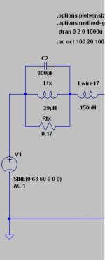
So if I am going to model this with LTSpice, should I model the transformer to be an ideal voltage source in series with the parallel of H=28.8uH (44.8uH for the other), R=0.15 (or 0.225R?) and C=? (to be worked out)? Please see an illustration in the attached picture.
Thanks.
When shorting the primary to measure the leakage inductance, on one secondary the reading was 28.8uH, on the other secondary it was 44.6uH. Is that normal? Is there anything wrong? Should they be identical?
When shorting the secondary windings to measure the leakage inductance from the primary side, the reading was 1.06mH. This is much higher. Should leakage inductance be the same when measuring from either the primary or secondary side? I must be somehow wrong, as the leakage inductance is unlikely that high.
One secondary winding gives a stable 0.15R reading, and the other jumps around between 0.14R to 0.15R. Does it mean there is some inbalance? The primary has 2.09R.
When I entered these numbers into PSU2, it works out that the transformer can deliver 10A on each of the secondary, with a Source Resistance = 0.225R.
I also connected the signal generator with a 1k resistor in series on the secondaries and measured the voltage developed across the coils and found the resonant frequency to be 910kHz for both secondary windings. So when I return to work tomorrow with a much better calculator I can easily work out the leakage capacitance very easily.
So if I am going to model this with LTSpice, should I model the transformer to be an ideal voltage source in series with the parallel of H=28.8uH (44.8uH for the other), R=0.15 (or 0.225R?) and C=? (to be worked out)? Please see an illustration in the attached picture.
Thanks.
Attachments
Last edited:
Leakage inductance strongly depends on how the transformer has been winded. So, don't worry about that difference. The winding nearest the primary will have the lower leakage, and in a power trafo usually don't care too much.
Each winding will have its own leakage inductance. It may vary a bit between two nominally identical windings. Leakage inductance tells you how much of a winding's flux is not linked to other windings. It is a measure of flux linkage or (lack of) coupling.
Remember with a transformer any impedance will be transformed when measured from another winding.
Remember with a transformer any impedance will be transformed when measured from another winding.
Were you measuring the inductance with a frequency close to the operating frequency?
I think the LCR metre measures L at 500kHz. I think that should be good enough.
Remember with a transformer any impedance will be transformed when measured from another winding.
Thanks. So that is the reason I got different readings when measuring from the primary or secondary side.
500kHz 😱
500 KHz and power transformer shouldn't be mentioned in the same phrase.
I think it must use a *much* lower test frequency.
Say, 400 Hz or something.
500 KHz and power transformer shouldn't be mentioned in the same phrase.
I think it must use a *much* lower test frequency.
Say, 400 Hz or something.
I measured both secondary windings having a resonant frequency at 910kHz. If I use the formula F = 1 / (2 * Pi * SQRT(L * C)), I would have the leakage capacitance C = L * square(1 / f) / (2 * Pi). Here f = 910000. Should I use the leakage inductance for the L?
If so, since I have 28.8uH and 44.8uH leakage inductance on the 2 secondary windings respectively, the leakage capacitance turn up to be 1044pF and 672pH respectively. Does it sound right to you?
If so, since I have 28.8uH and 44.8uH leakage inductance on the 2 secondary windings respectively, the leakage capacitance turn up to be 1044pF and 672pH respectively. Does it sound right to you?
Last edited:
I am still thinking about how an equivalent circuit looks like in LTSpice.
Looking from the power supply side, I presume the circuit sees the transformer's secondary leakage inductance, leakage capacitance and winding resistance.
For a good approximation only, can we ignore other parameters hence saving the efforts of modelling the primary side? Would this approximation be good enough to use to design a PSU?
If so, can I model the transformer as an ideal voltage source in series with the parallels of leakage inductance, leakage capacitance and winding resistance? or the inductance and resistance are in series, then in parallel with the capacitance?
Real transformers are usually modelled as ideal transformers with added parasitics, such as leakage inductance and capacitance.
A transformer is not a voltage source. Ultimately it is a pair of coupled inductors, so that is where you have to start from.
A transformer is not a voltage source. Ultimately it is a pair of coupled inductors, so that is where you have to start from.
Real transformers are usually modelled as ideal transformers with added parasitics, such as leakage inductance and capacitance.
A transformer is not a voltage source. Ultimately it is a pair of coupled inductors, so that is where you have to start from.
You can set it up as a voltage dependent current source, then add the parasitic elements.
Here's the method which Christophe Basso describes in his book "Switch Mode Power Supplies"
1) inject a sinusoidal voltage Vp on the primary and measure the open circuit voltage on the secondary, Vs. The turns ratio is then:
N=Vp/Vs
2) Measure the primary inductance with open secondary at 1kHz = Lpsopen
3) Measure the primary inductance with secondary shorted @10kHz = Lpsshort
The coupling coefficient is
k= SQRT (1-(Lpsshort/Lpsopen))
the leakage inductance follows:
Lleak(primary) = (1-k)*Lpsopen
Lleak(secondary) = (1-k) Lpsopen/ N^2
the magnetizing inductance is
Lm= k * Lopen
The ideal transformer LTSpice model is available from some of the diyAudio forum threads. I have got it too. It does not model parasitics.
I read "Calculating Optimum Snubbers" by Jim Hagerman, and when calculating the snubber he only used the leakage inductance and the interwinding capacitance as a lumped capacitor in parallel with the inductance. If that works it means we don't need to be concerned with Lpsopen, Lpsshort, etc.
So I am wondering if I can simply model the transformer as an ideal voltage source in series with the "transformer secondary", the later is simply modeled as a lumped interwinding capacitance, interwinding resistance and leakage inductance, with an even more simplied model of having the 3 in parallel, as I gave in the picture of my original post.
Would it work?
Thank you for your posts.
The ideal transformer LTSpice model is available from some of the diyAudio forum threads. I have got it too. It does not model parasitics.
I read "Calculating Optimum Snubbers" by Jim Hagerman, and when calculating the snubber he only used the leakage inductance and the interwinding capacitance as a lumped capacitor in parallel with the inductance. If that works it means we don't need to be concerned with Lpsopen, Lpsshort, etc.
Look at the equations, and you tell me if it will work.
At any rate, I find the question of snubbers on the secondary pretty tedious for analogue applications. You should probably look at the rectified and filtered waveform under load and see if you have an issue before investing a lot of time trying to fix it.
For SMPS, I can see where the energy released during the switching transient could pose a threat to navigation...
It all came from putting the probe of my scope onto the rails and found 8mV ptp noise and resonances at around 900kHz, which happens to be close to the resonant frequency of the secondary windings of a similar transformer I measured separately yesterday. Is the transformer itself causing the noise? or is it caused by the diode on-off switches?
It is a mystery I want to find out. I think using LTSpice is good at it but want to be sure I can model it approximately correctly, even if the result is approximate.
It is a mystery I want to find out. I think using LTSpice is good at it but want to be sure I can model it approximately correctly, even if the result is approximate.
Last edited:
I built a little test jig, basically a copy of Figure 16.10 in Bob Cordell's book (p.353), that lets me directly observe the LC ringing of a power transformer's secondary leakage inductance, secondary capacitance, and rectifier capacitance. My board includes a socketed 25-turn trimmer potentiometer, which lets me adjust the snubbing resistance while observing the oscillatory, ringing waveform. In effect I can slowly dial up any damping factor zeta I wish. To complement the snubber paper by Jim Hagerman, here is Wikipedia's article about zeta: Damping ratio - Wikipedia, the free encyclopedia
The slick part of Cordell's circuit is, it allows you to measure the LC ringing while running the transformer at the real-life operating frequency (2X AC mains: 120 Hz in USA), with real life rectifiers and real life load current. Furthermore, the optimum snubber resistance found with this measurement technique, transfers directly over into the final end application, since you're using the same transformer in the same way. Finally, for those who hate equations and algebra (me, personally, I love em both, but many do not), this is a measurement with no calculations, no equations, and no algebra. Twirl the adjustment screw till you get a waveshape you like. Unplug the trimpot from its socket and measure the R on your ohmmeter. Done.
I selected rectifier diodes for this board, that are especially slow (long tRR). Slow diodes give the largest signal amplitude on the oscilloscope. Fortunately, the oscillatory frequency is almost completely determined by the transformer itself, and the diode capacitance plays a tiny role. So measuring with one diode, while building end-product with another, introduces very little error. Especially if you use the 2C, 1R snubber as discussed next. To hedge my bets and to give more flexibility, I laid out the diode footprint to accept both the DO-201 axial package, and the TO-220-2 vertical package. All of the cool Schottkys and HEXFREDs and MUR1520 Ultrafasts and Fairchild Stealth soft recovery diodes, are in the TO-220-2. On some future date, if I feel so inclined, I can populate a board with some of these other diodes, and repeat the measurements. Theory says it won't matter.
Pro tip: Hagerman discusses the 2C, 1R snubber starting on about page 8. This has the great advantage of rendering the transformer's secondary capacitance irrelevant, by installing a large (dozens of nF) capacitor in parallel. Now Ctotal = Cexternal + Csecondary = Cexternal, regardless of the puny secondary capacitance inside the transformer itself. (It also reduces the frequency of oscillation, as Hagerman points out). So your optimum snubber is now insensitive to unit-to-unit variability in secondary capacitance. Or as other posters have remarked, it is insensitive to capacitance variations among different secondary windings on the same core. So I included this second capacitor on my board. I can populate it or not, as I see fit. (I fabbed 10 copies of the board, the min order at that shop).
I happen to subjectively prefer the waveshapes I get when zeta is about 0.8, which is not what Hagerman (0.5) recommends, nor is it Prof. Butterworth's theoretical ideal value (0.707) that you learn in second order linear systems analysis in your EE-201 class at university. Hey, it's a human preference. You are free to pick your own favorite zeta.
Last edited:
Thanks for the write up and sharing your experience.
I was thinking in the same way as you did by introducing 22nF across the diodes as well as hundreds of nF connecting the secondary to ground before the bridge rectifiers.
The interesting thing is I got exactly the same results as you and Hagerman wrote on the paper in my simulations using the equivalent circuit given by Hagerman.
But wait a minute. Hagerman's equivalent circuit has the Ct (transformer secondary winding capacitance) connecting the secondary winding to ground, but has the inductance and resistance in series with the circuit, hence the corresponding simulation results. I think it is not entirely accurate because in that case the capacitance shunts noise to ground but in real situation the capacitance can actually pass (bypass the resistance and inductance) high frequency noise (from the mains coupled to the secondary) from the secondary to the circuit! So I thought I would give it a try to put the capacitance in series.
Now if I put the leakage inductance, winding capacitance and resistance in parallel and then connect in series with the circuit as I guess they can be, I don't find any resonances like what I previously simulated!!! I find a bump below 100Hz that requires a 0.05R resistor to fix.
So this is still about finding the correct equivalent circuit to model the transformer parasitics to make it useful in simulating a power supply.
My plan is to put the PCB copper at the top and reserve the space for one or two RC snubbers, so that I can install trimpots and swap parts when measuring the noise.
HiFiNutNut,careful with your equations, i think your missing a 2^2 and pie^2.I think it's something like this:C = 1 / (4 * pie^2 * L * freq.^2)Cheers,Chris
HiFiNutNut,careful with your equations, i think your missing a 2^2 and pie^2.I think it's something like this:C = 1 / (4 * pie^2 * L * freq.^2)Cheers,Chris
Thanks. You are right. I did not calculate it wrongly. I wrote it down in my post wrongly.🙂
I think the hardest bit is to model the power supply correctly.
The transformer secondary winding is a lumped element of inductance, resistance and capacitance, while we tried to simplify it to 3 individual components. I guess that may be where I have gone wrong.
Other things have not been modeled, such as the power line input impedance, primary winding LCR, etc. I use a voltage source plus the inductance, resistance and capacitance of the transformer secondary, that may over simplify the picture.
But I must come up with a simple (or simplified) but effective model to come up with some good approximates.
I built a little test jig, basically a copy of Figure 16.10 in Bob Cordell's book (p.353), that lets me directly observe the LC ringing of a power transformer's secondary leakage inductance, secondary capacitance, and rectifier capacitance. My board includes a socketed 25-turn trimmer potentiometer, which lets me adjust the snubbing resistance while observing the oscillatory, ringing waveform. In effect I can slowly dial up any damping factor zeta I wish. To complement the snubber paper by Jim Hagerman, here is Wikipedia's article about zeta: Damping ratio - Wikipedia, the free encyclopedia
I have had a look at that schematic in Bob Cordell's book. That is something I may do. Thanks for the tip. It does add a 0.1R in series hence provides some damping that may slightly alter the result.
I am wondering if I can measure it while the PSU is powered off, and inject signals of various frequencies via a 1k resistor directly onto the secondary winding terminals. I then use a scope to probe on various points on the rails and observe any peakings.
Would it work?
- Status
- Not open for further replies.
- Home
- Design & Build
- Parts
- Making sense of transformer measurements