Changing between ceramic and polyester should not alter the sound in a dramatically noticeable way. I doubt you would pick it up on an ABX test tbh.
If the sound is not right, then something is amiss with the caps.
If the sound is not right, then something is amiss with the caps.
Maybee caps were defect because of their age...
I would like to join preamp and LPF in single enclosure.
Can I connect preamp to +12v and gnd of LPF power supply or will this make to much change between +12 and -12 rails for LPF? Transformer is 1.5A
I would like to join preamp and LPF in single enclosure.
Can I connect preamp to +12v and gnd of LPF power supply or will this make to much change between +12 and -12 rails for LPF? Transformer is 1.5A
You can connect the preamp to the +12 volts. It only draws a microscopic current. Also rail imbalance (even like +6 and -30 or +30 and -6) would not alter the DC conditions, it would only cause assymetrical clipping.
Ok, thank you for that.
I have one last wish to made. (Again hehe).
Now I have nice preamp, nice LPF, and I figured out that still need bass boost.
I remembered what is it like when I have bass boost turned off in my car and what is like when I turn it on.
I don`t know at what frequencies do bass boost work. I readed that from 40hz to 60hz?
I`m not talking about bass boost that you get on cheap mini-hifi devices (I think that they have passive circuit that just make highs less loud), but a bass boost that you get on car amp or good active sub.
So my question is how can I build opamp circuit that would boost 40-60hz up to 12dB, either controlled by switch (0db-6db-12db) or by potentiometer 0 to 12dB
Thank you.
Bass booster would need to accept -4db signal, because LPF already have boost of 6dB, so thats -10db + 6bd = -4db and boost it for aditional 12dB.
I would use +12v -12v power supply and NE5532 or TL072.
Thank you.
If my logic works correct I could also use simple passive bandpass filter to attenuate frequencies from low to 40 and 60 to high right?
....EDIT....
After some more search I found that bass boost is nothing more than a bandpass filter followed with op-amp, or is it?
For example if I need 12db boost at 40Hz to 60Hz I build bandpass filter that will attenuate from 20hz (or even lower for subsonic filter effect) to 39Hz and from 61Hz to the end of audio spectrum for -12dB and than add opamp with 12dB gain after the filter (which happens to be the exact same circuit that I used for preamp, just without imput filtering).
Again as with the LFP It`s hard to made adjustable one, because I would have to change attenuation from -12db to -6db and opamp gain from -12db to -6db at the same time right?
I just need to find a way to keep filtered frequencies from going lower than -12dB... this could be made by bypassing whole bandpass filter with a resistor , but I don`t know how to calculate the value of resistor for -12dB attenuation...
I feel like that I`m finaly getting somewhere with this opamp theory 🙂
This would be the right way, right?
Last edited:
A band pass filter passes frequencies within its design range. For example between 1kHz and 5 kHz (or whatever limits you set.
The attenuation of out of band signals depends on the exact design of filter.
You will find this interesting (if you haven't already got this).
The attenuation of out of band signals depends on the exact design of filter.
You will find this interesting (if you haven't already got this).
Attachments
Hello,
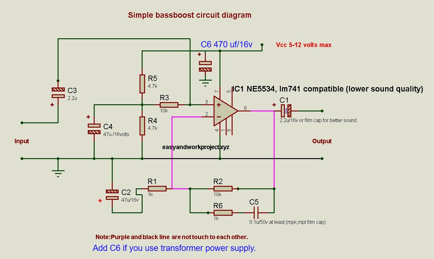
I was lucky and found completed bass boost circuit on the web.
I will do a testbuild on protoboard. It should be good.
I was lucky and found completed bass boost circuit on the web.
I will do a testbuild on protoboard. It should be good.

I made it and I get 5vdc on the input... any suggestions?
But I used 4558 could this be the problem?
But I used 4558 could this be the problem?
Last edited:
You will do if you are using it on a single rail power supply, that's ok, the output capacitor blocks the DC
I have found the problem...
I overlooked that circuit is made for NE5534...
However I changed the connections for the right pinout for NE5532, 4558, ...
It was the same 5vdc at the input, i added 10k resistor and dc at the input dropped to 0,7vdc.
Now the problem is that bass is really distorted.
I think that gain is way to high... I should change r3, r4 and r5 right? but to what values?
My bad. Now i seen that i should change r1 or r2
I changed r1 to 5k5 for a test and its not distorting anymore 🙂
I guess that I can use .33uF and 470k for input filter like on LFP
If you are using single rail then the two input pins and the output pin of the opamp should always read the same voltage and all should be at one half of the supply.
If that isn't happening then you have a basic error in the construction/circuit.
If that isn't happening then you have a basic error in the construction/circuit.
Yes it was error in the circuit. It's good now
Actually what I get is 5vdc on input and output when I connect multimeter, but when I connect it dc starts to fall and it falls under 100mv eventualy. Can I add 10k from input to gnd and 100k (load resistor) from output to gnd.
I tried with 10k from input to gnd and voltage stays at 0. But I'm not sure if this would change the sound or not?
Its probably best if you now post the circuit you are actually using (component values and reference numbers) so that we can be clear on what is happening.
You should see a constant 'half supply' voltage on all three relevant pins of the opamp, that is the - input, the + input and the output. If that isn't happening then you have a problem.
You should see a constant 'half supply' voltage on all three relevant pins of the opamp, that is the - input, the + input and the output. If that isn't happening then you have a problem.

Circuit is for NE5534, but I adopted the pins.
I`m actually almost complete with the circuit on the stripboard, with one exception, for C5 I have 3 capacitors (0.2uF, 0.3uF and 0.4uF so I can adjust the boost center frequency -40hz, 60hz and 80hz) and a selector switch.

It`s not exactly what I was going for because boost is not equal, but I can live with that. I will still have some level of control to adapt do different subwoofers and music styles. 🙂
Ok, it`s finished, there is zero DC at input and output with source and LFP connected.
It makes bass sound more full. I`m happy with the resoult.
Thank you for help 🙂
Ok, it`s finished, there is zero DC at input and output with source and LFP connected.
It makes bass sound more full. I`m happy with the resoult.
Thank you for help 🙂
- Status
- Not open for further replies.
- Home
- Amplifiers
- Chip Amps
- Making preamplifier...