390k or 510k or 430k will all do fine.
The filter RC is R value * C value
The -3dB roll off frequency is 1/2/Pi/RC
if you want/need full bandwidth audio right down to 20Hz then the F-3dB passive input filter should be set to ~ 1 decade lower, i.e. 2Hz.
If you use an electrolytic, then to avoid distortion go another octave lower.
The filter RC is R value * C value
The -3dB roll off frequency is 1/2/Pi/RC
if you want/need full bandwidth audio right down to 20Hz then the F-3dB passive input filter should be set to ~ 1 decade lower, i.e. 2Hz.
If you use an electrolytic, then to avoid distortion go another octave lower.
What would happen if I use 400k or 500k instead of 470k? I don`t have 470k right now.
Actually 660k is closest that I have
390k or 510k or 430k will all do fine.
The filter RC is R value * C value
The -3dB roll off frequency is 1/2/Pi/RC
if you want/need full bandwidth audio right down to 20Hz then the F-3dB passive input filter should be set to ~ 1 decade lower, i.e. 2Hz.
If you use an electrolytic, then to avoid distortion go another octave lower.
I will change to 660k now.
No I used ceramic capacitors, so I don't have to worry about distortion.
390k or 510k or 430k will all do fine.
The filter RC is R value * C value
The -3dB roll off frequency is 1/2/Pi/RC
if you want/need full bandwidth audio right down to 20Hz then the F-3dB passive input filter should be set to ~ 1 decade lower, i.e. 2Hz.
If you use an electrolytic, then to avoid distortion go another octave lower.
What values would I need to use for full bandwith down to 20hz?
You could try regulating the output from the SMPS, see if the buzz goes then
I already built supplyes for both preamp and LFP, so I won't be using smps.
No I used ceramic capacitors, so I don't have to worry about distortion.
Oh, OK then 😛
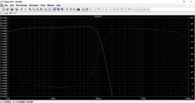
The response goes almost all the way down to 1Hz if you use a 0.33uF cap and a 660k
Attachments
Ceramics are among the worst capacitors for signal use
I used what I had at home. I won't be able to get new components till the end of holydays and I need crossover for new years party. It doesen't sound bad.
Oh, OK then 😛
The response goes almost all the way down to 1Hz if you use a 0.33uF cap and a 660k
Thats good 😀
It's about time that I learn making simulations with LTspice.
Last edited:
They'll do the jobI used what I had at home. I won't be able to get new components till the end of holydays and I need crossover for new years party. It doesen't sound bad.
Just click my signature line to see how its done 🙂
Here is the file in case you want a play. It will run straight off in LTIV or LTXVII
Thank you I will start tomorrow.
Do you know if BC104k is 0.1uF capacitor? I have some green poliester caps with BC104K written on them. I know that 104 is 0.1uF but I'm not sure what is BC. Can't find any info on internet about it.
The manufacturers are now making COG/NPO in larger values.
Look for MLCC COG ceramic capacitors.
For values around 1uF it's more usual to use plastic film like MKT/MKS/MKP etc
M indicates a metalised film whereas FKx is a metal foil alternating with the plastic film. These are bigger and expensive, but there some conditions where this construction gives improved performance (eg. extreme ampere/us).
Do not use the high K ceramics to pass audio signals. These HiK are excellent for local supply rail decoupling, look for X7R.
You don't need to learn a simulator to determine whether a passive RC filter is working for you or against you.
Just use the standard formula to predict frequency F-3dB = 1 / { 2 Pi RC }
Or turn that around to find a suitable RC = 1 / { 2 Pi Freq }
Last edited:
Merry christmas everyone!
I changed capacitors to poliester and bass is not kicking right / as much. It's just bummy.
I'm going back to ceramics, there was nothing wrong with the sound when I used them.
Thank you for the formula Andrew.
I changed capacitors to poliester and bass is not kicking right / as much. It's just bummy.
I'm going back to ceramics, there was nothing wrong with the sound when I used them.
Thank you for the formula Andrew.
that tells me you made a mistake.Merry christmas everyone!
I changed capacitors to poliester and bass is not kicking right / as much. It's just bummy.
I'm going back to ceramics, there was nothing wrong with the sound when I used them.
Thank you for the formula Andrew.
that tells me you made a mistake.
I dont know. There are only 3caps to change. Everything was soldered correctly, I always check twice.
I changed back to ceramics and is good.
- Status
- Not open for further replies.
- Home
- Amplifiers
- Chip Amps
- Making preamplifier...