I use a 2mV/div scope.
I cannot see 1mVpp of noise after subtracting the big signal.
All I have is a wider line where a thinner line should be, indicating there is noise and other interference on the big signal.
A scope won't measure noise of <1mVpp.
You need completely different tools to measure and compare noise levels from different circuits.
Look up Frex
http://www.diyaudio.com/forums/equi...llivoltmeter-recommendations.html#post4003402
or
LNA (low noise amplifier)
Hi and thanks again for the always valuable advice.
I am in the learning phase and i did not even know what are really my needs.
For instance, as i said before, i see people striving to get noise down to the uV to supply digital circuits.
I do not know if this is really needed.
Let's say that at first i will be gross.
I will start testing some cheap SMPS and see what comes out.
From what i read speaking of 12-24V SMPS usually the noise goes from 40-50mV for the best ones to even 200-300 mV for the cheapest.
I guess this level of noise can be seen on almost any scope around, also the cheapest ones. This will be my first approach with testing.
I have to start gross i guess.
In the meantime i have found a tutorial on youtube that i cannot see from here. But i will watch this evening.
https://www.youtube.com/watch?v=Edel3eduRj4
Because i am extremely interested in the noise filtering technique.
I was surfing the unbelievable Mouser catalogue and i saw some very cute TDK smps ... they are extremely handy.
And i was thinking, if i will be able to use the scope, to buy one of this and then play with some filters to see how much i can reduce the noise.
Just an idea anyway ...
Thanks again a lot, gino
Last edited:
Hi and sorry if it's me again.
Just to sum up the principles:
1) digital circuits are less sensitive to power supply noise
2) analog circuits are more sensitive to power supply noise
I agree completely on this and i thank you for the important advice indeed.
But in a dac ? we have both ...
In particular a dac chip where the digital becomes analog ... is it sensitive to power supply noise ?
are there any benefits from using a very very low noise ps ?
Another question, even more important to me ...
i am very interested in usb to aes converter ... where the process occurrs all in the digital domain let's say
Does this mean that a usb to aes converter is much less sensitive to noise coming from the power supply ?
It is very important to me to know this for sure.
And the i promise no more silly questions.
Thanks a lot again.
Kind regards, gino
In particular a dac chip where the digital becomes analog ... is it sensitive to power supply noise ?
Had you considered looking at some DAC datasheets?
i am very interested in usb to aes converter ... where the process occurrs all in the digital domain let's say
Does this mean that a usb to aes converter is much less sensitive to noise coming from the power supply ?
The converter isn't the issue- the question is the receiver.
Had you considered looking at some DAC datasheets?
Hi ! Do you mean dac chip datasheets ? ... no.
Looking now but i do not know what to look for ... 😱
The converter isn't the issue- the question is the receiver
Thanks a lot. The issue is the usb receiver chip.
I think it is one from Xmos ... could it benefit from a cleaner PS ?
I ask this because i see herculean efforts to keep the noise in the ps at unbelievably low levels even at high Hz.
and it is a very challenging task.
As i said i am quite convinced that the dac i am using is decent.
But it has no usb port and i am stuck with the pc as source for ever.
It is just too flexible and handy. Love it.
But it is also very tricky to set up rightly.
Thanks a lot again, gino
Last edited:
Hi ! Do you mean dac chip datasheets ? ...
Yes. At some point, you're going to have to actually learn something for yourself. It won't cause physical pain, I promise!
Yes. At some point, you're going to have to actually learn something for yourself.
It won't cause physical pain, I promise!
Ok ! but what i have to look for ?
I mean for a regulator i know that i have to look for instance to the PSRR vs. Hz, to say one ...
But for a DAC ? or better ... to see the influence that noise in the supply has on the chip performance ???
I honestly i do not know where to start.
I was looking to this one for instance ...
http://www.lampizator.eu/lampizator/LINKS%20AND%20DOWNLOADS/DATAMINING/tda%201543.pdf
there is no graph/table mentioning PS noise
Thanks and regards, gino
Get the datasheet for a DAC chip, and read it thoroughly until you understand how it works. It's really not that hard.
If you keep reading ad copy and try to make sense of it, then follow up by asking vague and half-understood questions over and over, you'll get nowhere.
Don't be this.
Ok ! message received.
But i am skeptical ... i am not that brilliant.
By the way i will try because this of the noise is a very fascinating subject.
Noise and distortion of course ...
Kind regards, gino 😱
Ginetto
digital is much more immune to noise than analogue... I may seem to be repeating this but it is true... earlier you used an example that was wrong you were confusing regulation (0.1% I believe you quoted with noise, different issue and also not required for most digital, data sheets for devices will give required regulation figures. Off the top of my head the Vtt supply for DDR memory is one of the most stringent for regulation levels, but you wont be DIYing a DDR interface any time soon).
Mains, there is already a lot of HF noise on the mains due to power line communications, some areas are worse than others.
The best way of achieving a quiet system is doing your own PCB as any modification to the digital side are often not going to achieve a lot as they tend to add more parasitics (inductive and capacitive) especially on decoupling. The next best thing is isolation between equipment, common mode and differential mode chokes on main supplies, power islands with "cap-ferrite-cap" pi filters, using LDOs to isolate critical supplies creating power islands (single contiguous GND plane is preferable isolated powers islands are a good thing though), using proper EMC techniques where signal enter and exit a board etc. (often a lot of this is missing from units I see for sale for audio applications!).
Reading up on Henry Ott and Ralph Morrison is a good start and getting to grips with coupling mechanisms for HF noise is also a good start.
There is an awful lot to noise control and creating the most effective power delivery system, it is also an area where solid engineering practices have to be used, getting basic digital decoupling correct is one of the first issues and here add on mods tend to be pointless due to added inductances....
So as a start investigate the main coupling methods for high frequency noise.....
I think it is one from Xmos ... could it benefit from a cleaner PS ?
This is the deepest hole you can get into.
Some say you can use a simple power wire for speaker wire and some pay 10000 for a power cable. Or more.
Then there are ppl saying they can hear if they put a wood block under the speaker cable so it doesn't sit on the floor. If you ask them, you should make everything the best. So yes, the to PSU for a USB-SPDIF transport is just as important as the power for the amplifier, or any other component. But there are some who can't hear these things and are just happy with it with USB power.
Simply you will have to test what can you hear, then if you can, then is it worth it. If not, then you only can't hear, because other components are not good enough to hear the difference, or it ust doesn't make a difference.
And so on. This is what hifi is about. Good luck 😀
Or maybe its just a matter of perception being fooled.
I'm sorry but to do power supplies and combat noise properly measurements are needed to give an indication of not only if there is a problem but in the case of noise the frequency spectrum of the noise... then if noise is present you can start looking for a solution.
I'm sorry but to do power supplies and combat noise properly measurements are needed to give an indication of not only if there is a problem but in the case of noise the frequency spectrum of the noise... then if noise is present you can start looking for a solution.
Ginetto
digital is much more immune to noise than analogue... I may seem to be repeating this but it is true... earlier you used an example that was wrong you were confusing regulation (0.1% I believe you quoted with noise, different issue and also not required for most digital, data sheets for devices will give required regulation figures. Off the top of my head the Vtt supply for DDR memory is one of the most stringent for regulation levels, but you wont be DIYing a DDR interface any time soon)
Hi and thanks a lot for the very important advice.
I have to fix some idea in my mind.
Mains, there is already a lot of HF noise on the mains due to power line communications, some areas are worse than others
and also this is extremely important.
I think i am getting mad on one point. I know for sure that toroidals have less filtering effect on mains noise of other type of transformer.
Why they keep using them ? why ?
I can understand for big VA ... toroidals are more compact for same VA
But for small VA ???
I have the feeling that a right selection of the transformer can make the filtering issue less critical. Even avoidable.
And i would have replaced immediately the transformer in my unit, if the space were not so little inside.
But i could even buy another bigger case ... this of course complicate things.
I have bought a transformer from Mouser like the one depicted below and plan to use it in place of the toroidal ...
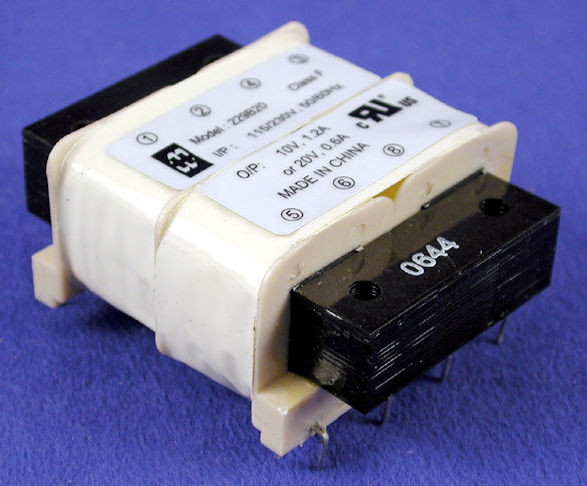
i would bet that the mains noise will be suppressed much more than with the toroidal.
This is just a part replacement ... and still worthwhile
The best way of achieving a quiet system is doing your own PCB as any modification to the digital side are often not going to achieve a lot as they tend to add more parasitics (inductive and capacitive) especially on decoupling
maybe i have not been clear and sorry because i have big problems with english.
Let me rephrase a little.
The unit as it is send a lot of noise from the mains on the main regulator on board that i am sure let much of this noise through.
I have no intention to touch anything on the pcb
My goal is to provide the regulator with the supply as cleanest as possible.
That's all. Nothing more.
And this of course implies to get rid of the noise coming from the mains.
Even just replacing the mains transformer with another one could be a good step in the right direction, like adding some kind of filters upstream the regulator.
Main constraint is the little space inside the unit. that is the real problem.
Because if not the toroidal would have been already in the garbage bin without any hesitation.
I do not know how much this will be benificial ... i feel a lot.
Because good part of the noise will never reach the regulator but it will stopped at the transformer level.
The next best thing is isolation between equipment, common mode and differential mode chokes on main supplies, power islands with "cap-ferrite-cap" pi filters, using LDOs to isolate critical supplies creating power islands (single contiguous GND plane is preferable isolated powers islands are a good thing though), using proper EMC techniques where signal enter and exit a board etc. (often a lot of this is missing from units I see for sale for audio applications!).
Reading up on Henry Ott and Ralph Morrison is a good start and getting to grips with coupling mechanisms for HF noise is also a good start.
There is an awful lot to noise control and creating the most effective power delivery system, it is also an area where solid engineering practices have to be used, getting basic digital decoupling correct is one of the first issues and here add on mods tend to be pointless due to added inductances....
So as a start investigate the main coupling methods for high frequency noise.....
I am sure that what you propose is right
But it is completely way beyond my reach.
Maybe one day with more spare time i could embark myself in a similar project ... but i see it extremely challenging.
I understand that modding something existing in this forum is not very popular. And i understand very well.
The more i look at this toroidal the more i hate it.
These are the mains transformers i would like to see instead in the ps.
Regards, gino
Attachments
Just curious, did you ever try to google "advantage of toroid transformer"? Or is typing into a search box a difficult task?
Yes i found more efficient, less dispersion of magnetic flux but also less mains noise suppression that is what i am interested in more
Ok .. the magnetic flux from a EI could be a problem if it is too close to the circuit
Unfortunately i have no access to the schematics of these supplies.
I should find a kit of this type.
In my unit there are no filters at all. Just a toroid > humble diodes bridge > caps before the regulator.
Not a big deal.
But as i said i do not have a scope ...
Regards, gino
Last edited:
fit a mains filter.
They are best when INSIDE an all METAL enclosure and that enclose is effectively OUTSIDE the circuit chassis.
The IEC socket with integrated filter meets that brief.
The METAL enclosure of the filter is fitted through a hole in the side of the Chassis. and electrically connected to the chassis all around the perimeter of the hole and the two bolt fixings. The plug fits into the plastic end cap.
The contents of the IEC filter are effectively OUTSIDE the mains Chassis. The interference that is attenuated remains OUTSIDE the main chassis.
Only the unattenuated remains fo the interference get inside the main chassis.
The IEC mains filter is the simplest solution.
There are many more elaborate and more expensive solutions.
Do some reading, even this Forum has Threads on Mains Filtering..
fit a mains filter.
They are best when INSIDE an all METAL enclosure and that enclose is effectively OUTSIDE the circuit chassis.
The IEC socket with integrated filter meets that brief.
The METAL enclosure of the filter is fitted through a hole in the side of the Chassis. and electrically connected to the chassis all around the perimeter of the hole and the two bolt fixings. The plug fits into the plastic end cap.
The contents of the IEC filter are effectively OUTSIDE the mains Chassis. The interference that is attenuated remains OUTSIDE the main chassis.
Only the unattenuated remains fo the interference get inside the main chassis.
The IEC mains filter is the simplest solution.
There are many more elaborate and more expensive solutions.
Do some reading, even this Forum has Threads on Mains Filtering..
Hi and thanks a lot and actually it is what i see more often in a digital units when a toroidal is used.
I will try one i have at hand in the weekend and listen.
I see also some discrete filter upstream the mains transformers using chokes and caps. Very interesting.

I will look at some chokes data sheets ... maybe i will find some application suggestions.
They are very common in serious dacd power supplies.
Thanks again, gino
Don't just limit your search to this site, there is plenty of information out there regarding mains filtering and EMC issues... Power line communications has an exemption from EMC certification because it is based on EMI....
Don't just limit your search to this site, there is plenty of information out there regarding mains filtering and EMC issues... Power line communications has an exemption from EMC certification because it is based on EMI....
Hi and thanks a lot again for the valuable input.
I was shocked by some graphs showing how little effective are most of the regulators at suppressing/rejecting HF noise ... almost no effect at all.
So filters are my new passion ... they seem to be unavoidable to get really low noise.
I swear i will look for some very simple schematics both for AC lines and DC lines and try to assemble something.
Measurements remain challenging unfortunately.
I cannot afford equipment like this ... now.
https://www.youtube.com/watch?v=pKXPqApOYfk
Thanks again, gino
Based on what you explain with the industry near you, I suspect you have a Power Factor issue.... You will need to check the types of noises, distortions in you mains... Common Mode and Differential Mode noises... These require different filters obviously...
I have built various filters over the years and finally decided to create the mains voltage instead of filtering it and now much happier...
IEC 1000-3-2 (1995)/EN 61000-3-2 (1995):
Specifies the limits for harmonic currents created by equipment connected to public low-voltage supply systems. EMISSIONS ....
AUDIO Equipment falls into Class A category....
Limits for Class A Equipment
Harmonic order Maximum permissible harmonic current
👎 (A)
Odd Harmonics
3.... 2,30
5.... 1,44
7.... 0,77
9.... 0,40
11.... 0,33
13.... 0,21
15 ².... n ²39 0,15 x 15/n
Even Harmonics
2.... 1,08
4.... 0,43
6.... 0,30
8.... ² n ²40 0,23 x 8/n
Your concern is the SUSCEPTIBILITY of your equipment....
Last edited:
- Status
- Not open for further replies.
- Home
- Amplifiers
- Power Supplies
- Mains filtering for a digital equipment.