Good choice, height wise it will fit nicely in the retex box also. EI should be less sensitive to DC on power line.
🙂 yea it's an "endless" hobby, always something to learn...
🙂 yea it's an "endless" hobby, always something to learn...
What would be a good way to measure or calculate the improvements of the modifications? It seems like a good idea to have a method of checking if a new design actually is an improvement.
hehe much ado about nothing.. If you live in an area with polluted mains, EMI filter would probably be measurable. Question is if it affects SQ to a significant level. Caps most likely will be on subjective level, easy cheap if you like it fine... The external voltage reg might come in handy for other things one never knows..
Well in the end the whole system will act as a spdif/toslink/aes/i2s digital source.
I do not know which kind of measurments are carried out on a cd player transport for instance.
Nothing that i can do by myself.
However i see many people relying on listening tests to decide if the mods have been beneficial or not, like listening to well know tracks and so on.
The idea is that if i replace parts with higher grade ones that should result in some kind of improvements, like for instance with caps replacement if the better ones are not fakes of course.
My main goal is to improve mains noise filtering with a type of transformer known to be better at this than common toroidals.
Problem as usual is space available in the box ... they build such small boxes that i do not understand why.
Last edited:
Small box=cheap & cheaper shipping...
With ready made units the most important factors layout/chips are pretty much locked, guess you can cut ground planes, scratch varnish on traces/ground to place smd decoupling closer to pins on bad designs etc. "Modding" the PS can have good effects on DACs, plenty of threads on this forum all can't be wrong (even if most are done on china things where there is plenty of room for improvement
 ). Since all caps have different characteristics they ought to change the SQ somewhat (Can't see anything bad in trying a couple with suitable characteristics and picking a favourite even if its a little audio-voodo-ish) but there probably is not much to measure, unless you make really bad choice like putting ultra low esr to the input/output of a voltage reg that can't handle it causing oscillation etc etc . At the end of the day the important thing would be if you like the sound of your equipment.
Next level is learning how to make one yourself.
With ready made units the most important factors layout/chips are pretty much locked, guess you can cut ground planes, scratch varnish on traces/ground to place smd decoupling closer to pins on bad designs etc. "Modding" the PS can have good effects on DACs, plenty of threads on this forum all can't be wrong (even if most are done on china things where there is plenty of room for improvement
Next level is learning how to make one yourself.
This is why we now ALL should use a Mains Bulb Tester to power ON every new or modified mains powered project.Hi ... because i am worried to exchange the + and - of the two secondary
An externally hosted image should be here but it was not working when we last tested it.
This is enough for me to try with just one secondary connected and the other left open/unused
and see what happens
Looking at the secondaries if their terminals are not market + and - what would happen if i connect the + of one secondary with the - of the other and the same for the other terminals ?
Instead using just one secondary i will not have the least problem for connection.
I have never understood the phase issue ... never.
Regards, gino
The bulb will protect the transformer from damage no matter what errors you make in wiring up the primary and/or secondary windings.
This is why we now ALL should use a Mains Bulb Tester to power ON every new or modified mains powered project.
The bulb will protect the transformer from damage no matter what errors you make in wiring up the primary and/or secondary windings.
Hi and thanks for the advice and i am of course very interested.
And i will search in the forum for information about this safety device.
But i wonder if there is some kind of safety breaker that could be used instead. I do not know the English name ... one of the kind used at home.
A safety breaker ? i would buy one to use on the lab bench if i knew the model and right rating.
An externally hosted image should be here but it was not working when we last tested it.
i am not comfortable with bulb ... i hate tubes for instance. They can always explode.
Regarding the topic i wonder if there is a frequency range in which noise from the power supply could be extremely nasty for a digital device.
For instance i saw noise figures up to 100kHz ... is this enough ?
Maybe noise in the region of the MHz could be devastating for the overall performance of a dac/cd player/interface ...
Thanks a lot, gino
Last edited:
If you don't use the Mains Bulb Tester, to power ON a new project, you run a seriously increased risk of damaging something.
Have you read any of Marce's posts?.................Regarding the topic i wonder if there is a frequency range in which noise from the power supply could be extremely nasty for a digital device.
For instance i saw noise figures up to 100kHz ... is this enough ?
Maybe noise in the region of the MHz could be devastating for the overall performance of a dac/cd player/interface ...
Thanks a lot, gino
The big advantage of digital when properly designed is it's tolerance to interference and that it continues to work in the presence of many interfering fields.
That advantage is so big that many will accept much lower quality performance simply to gain that tolerance to interference.
How many have you heard complain about noise of Vinyl replay and make the comparison to CD's near noiseless reproduction? Same for comparing AM & FM radio to digital radio/internet streaming.
If you don't use the Mains Bulb Tester, to power ON a new project, you run a seriously increased risk of damaging something.
Hi and thanks again. But i would like to know if there is an off-the-shelf approved an tested unit to be sure that is effective.
I have read of a guy who was building one on a wrong schematic.
That i would like to avoid.
Have you read any of Marce's posts?
The big advantage of digital when properly designed is it's tolerance to interference and that it continues to work in the presence of many interfering fields.
That advantage is so big that many will accept much lower quality performance simply to gain that tolerance to interference.
How many have you heard complain about noise of Vinyl replay and make the comparison to CD's near noiseless reproduction? Same for comparing AM & FM radio to digital radio/internet streaming.
sorry but it is 3 weeks now that i read threads about super regolators with noise in the range of tenth of uV to be used specifically with digital devices.
Are they stupid ? all of them ?
When i proposed a regulator with noise around 0.3mV someone got offended.
They are all insane ? just to understand on which side is the truth
Thanks, gino
Last edited:
Perhaps it is a case of noise, noise or noise.
Gino, you seem to be targeting the noise at the input of the regulator from the mains when others may be trying to limit the noise that is generated by the digital devices or the regulators.
My opinion is that a DAC should be seen as an analogue device and sensitive to noise as any other analogue circuit. Data transfer is completely different. For example, if you are using an USB port then its like rush hour traffic with nearly every device in your computer using the same road. For me this is one of the reasons I still like my CD players with its own dedicated path from disc to amp.
Perhaps it is a case of noise, noise or noise.
Gino, you seem to be targeting the noise at the input of the regulator from the mains
Hi and yes but no. In the end what matters is the feed to the digital devices.
But from the comments it seems that everything that sits upstream the regulator has no effect ... the type of transformer, the diodes used, the caps used, the presence of mains filter or not.
Is this true ? that nothing upstream matters ?
i was thinking that instead everything matters but i am not sure
Clearly if the only thing that matter is the regulator i will only replace the caps because i have already taken out the original and waiting for the new ones to arrive, but i will leave everything else as stock.
Because for instance:
1) adding a mains filter
2) replacing diodes with Schottky ones
3) changing transformer type and rating
will have no effect at all. It would be a silly and expensive thing
Much more reasonable to try a better regulator instead.
But this would be much more difficult and i will not do this.
when others may be trying to limit the noise that is generated by the digital devices or the regulators.
yes but this is too difficult for me. The pcb is all smd aside diodes and caps.
I will not touch anything smd. I have no chance with smd parts at all.
My opinion is that a DAC should be seen as an analogue device and sensitive to noise as any other analogue circuit.
there is only a way to see. Injecting noise of different level and Hz and see what happens ... at certain Hz i have a feeling ... a disaster ... a nightmare.
Just think a noise from the supply of the same Hz of the oscillator ...
And these kind of frequencies can be present after the regulator ... but i would like to see for myself.
I think that this test would be very interesting to perform.
Data transfer is completely different. For example, if you are using an USB port then its like rush hour traffic with nearly every device in your computer using the same road. For me this is one of the reasons I still like my CD players with its own dedicated path from disc to amp.
this i can agree easily. Data transfer can be performed without big problem.
Maybe are not the data that are bad, is the dac that is fed with noisy supply that works badly.
I even dare to say that give a dac/clock a perfectly clean supply and any at least dac will sound excellent, multibit o DS or bitstream or whatever.
As an example ... look at the power supply of this cd player ... and it sounds pretty good ...
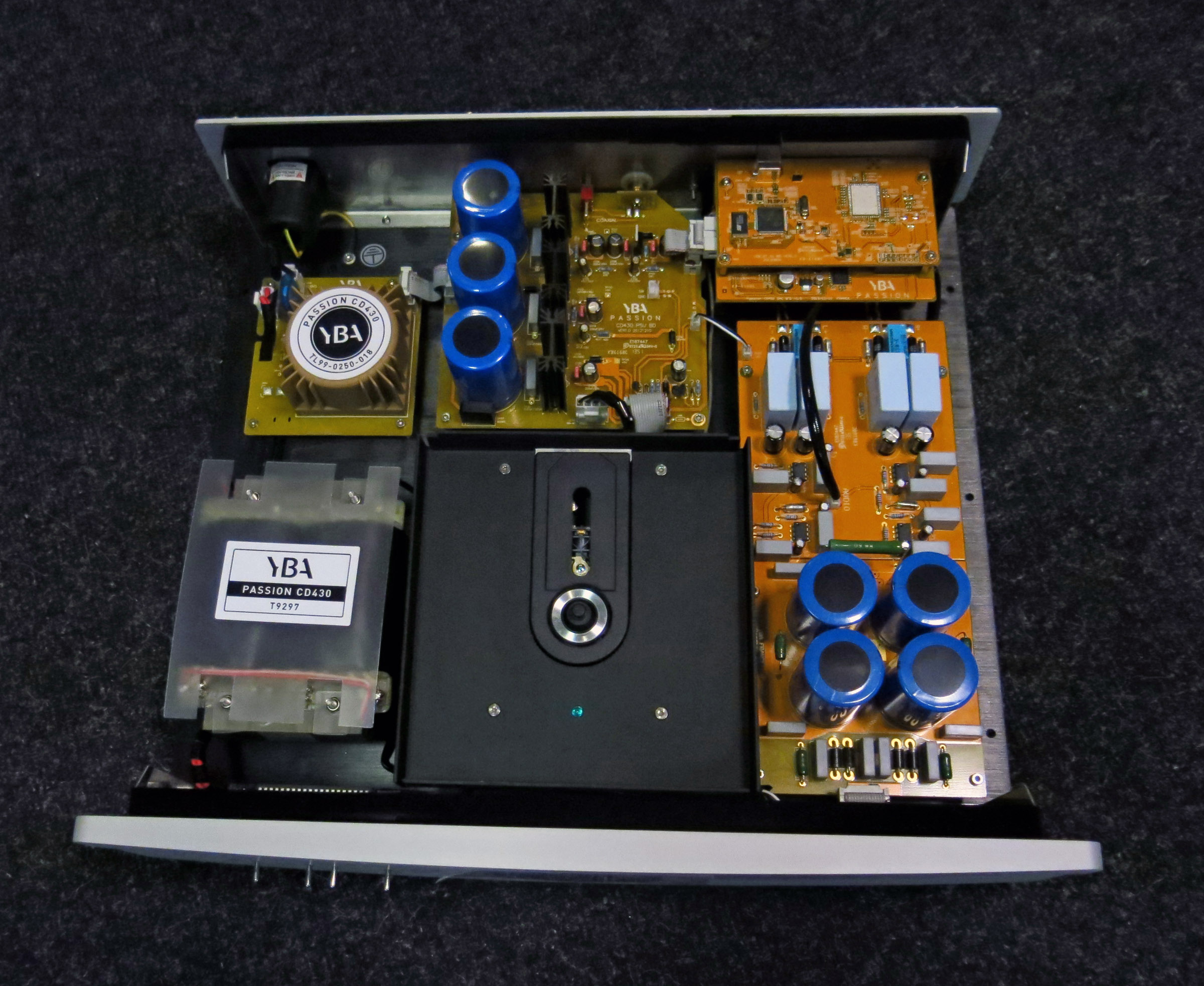
Thanks again, gino
Last edited:
You probably already spotted this thread Mark Johnsson's PhaseDots tester (might come in handy for others later):
http://www.diyaudio.com/forums/powe...rmer-phasedots-no-scope-signal-generator.html
Here is a discussion starting about applying low noise regulators to an already well regulated DAC (not finished yet so keep following):
http://www.diyaudio.com/forums/vend...e-r-2r-sign-magnitude-24-bit-384-khz-282.html
I think you can notice a difference with the changes you plan to apply. Are you going to test the regulator board?
If you plan on using the china-reg and worried about hf noise, use external diodes (like the bridge you mentioned in thread start) > large reservoir cap > choke of choice > DC in on the regulator board can be a worth a try.
You probably already spotted this thread Mark Johnsson's PhaseDots tester (might come in handy for others later):
http://www.diyaudio.com/forums/powe...rmer-phasedots-no-scope-signal-generator.html
Here is a discussion starting about applying low noise regulators to an already well regulated DAC (not finished yet so keep following):
http://www.diyaudio.com/forums/vend...e-r-2r-sign-magnitude-24-bit-384-khz-282.html
Hi and thanks a lot again for the very kind and precious advice.
I think you can notice a difference with the changes you plan to apply.
let's say that i hope. In the meantime i have found in the lt1963 datasheet an impressive, in the bad way, graph that i am attaching.
Practically any noise > 100kHz will pass the regulator "almost" not attenuated ?
Is this the evidence of the poor performances of some (or all) regulators at higher Hz ?
i am shocked ...
Are you going to test the regulator board?
that would be both smart and nice. I cannot. I have no instruments.
As i said in order to avoid irreversible disasters i will leave the pcb and parts on it as stock. Ps caps aside of course.
Clearly is not a serious approach ... it is more a silly game of mine 😱
If you plan on using the china-reg and worried about hf noise, use external diodes (like the bridge you mentioned in thread start) > large reservoir cap > choke of choice > DC in on the regulator board can be a worth a try
Yes that is indeed the idea. To block at least part of the HF noise from entering the regulator and avoid added noise from the diodes switching using Schottky type
I was thinking also to some kind of RC or LC filter on the regulated line before the regulator but i should have a working schematic to follow.
Like a service manual and so on.
So yes the idea is to block this hf noise before the regulator.
If this hf noise is detrimental, as i assume, i just wonder what i could get from som chinese dacs that sound already interesting but have exceptionally poor power supplies 🙄
i mean ... cheap toroidals and poor diodes.
A very good transformer (low V and VA) costs no more than 20 USD
A fist of Schottky diodes 5 USD ... on top of that put some Nichicon FG ...
i said that i am curious ?
Of course a good scope would be also nice.
But this has to wait a little.
For sure when i will be retaired (and hopefully not retarded) i will dedicate more time .. a lot more actually.
I was not bad at chemistry in the lab with instruments ... so maybe i could do something also with a scope.
I remember the 1st time ... i was 13 when i saw the 1st scope ... i was amazed by this thing.
Then i chose chemistry ... and i was scared 😱
Bad choice indeed. Very very bad choice.
With a bulb tester i understand working on electronics (avoiding tubes that i hate) is quite safe
With chemistry you never never know ... just a leak and bam ... disaster ...
Thanks a lot again. Kind regards, gino
Attachments

Last edited:
sorry but it is 3 weeks now that i read threads about super regolators with noise in the range of tenth of uV to be used specifically with digital devices.
Are they stupid ? all of them ?
When i proposed a regulator with noise around 0.3mV someone got offended.
They are all insane ? just to understand on which side is the truth
Noise reduction needs a system-wide perspective, not just looking at individual numbers.
For example - what use is a sub-uV power supply module that connects over unshielded wires a distance half a metre away from its load? That would suggest to me that the whole system hasn't been considered in the quest for noise reduction as all wires are antennas.
Another thing to ponder is the purpose of having a very low noise reg module when the self-noise of the digital electronics its intending to power is potentially two or three orders of magnitude higher than the output noise of said module.
LTspice is a good and cheap way to understand how circuits work and how to measure them. It may give you the answers you are looking for.
http://www.linear.com/designtools/software/demo_circuits.php
http://www.linear.com/designtools/software/demo_circuits.php
Last edited:
Noise reduction needs a system-wide perspective, not just looking at individual numbers.
Hi and thanks again for the helpful advice.
But now i know that i cannot expect a great rejection from that regulator of HF noise, assuming that HF noise is detrimental. Is it detrimental ? 😱
However, if i block this HF noise before the regulator ... bam ! the regulator will have not to deal with it.
I am sure that in my device a lot of this HF noise passes through the regulator to the circuit.
Maybe (but i cannot understand this) there are other filters/regulators after the lt1963 that is the 1st and main one.
This i do not know ... but i will try to spot.
For example - what use is a sub-uV power supply module that connects over unshielded wires a distance half a metre away from its load?
That would suggest to me that the whole system hasn't been considered in the quest for noise reduction as all wires are antennas.
I feel you are completely. If i had a scope i could see it clearly, i think.
And this would be the educated approach ... using the scope first and locate where noise is. Only then apply some mods and see again in the scope.
Anyway i will keep the mods to an absolute minimum. I swear 😱
Another thing to ponder is the purpose of having a very low noise reg module when the self-noise of the digital electronics its intending to power is potentially two or three orders of magnitude higher than the output noise of said module
I see your point and i agree. But is there any way to attenuate this self-noise ? in a negative case we can only provide them the cleanest power possible .. put them in the best conditions to work, without exaggeration.
Maybe this self-noise is related also to the supply noise ?
I have bought a kit based on this lt1963 ... to put upstream the existing one.
The stated performance at 100kHz are quite good ... so i guess they have used some kind of additional filtering around the regulator.
As soon as i receive it i could post some picture to understand the circuit.
And maybe to modify it for better performance ? 😀
Thanks a lot again, gino 🙂
LTspice is a good and cheap way to understand how circuits work and how to measure them. It may give you the answers you are looking for.
Linear Technology - LTspice Demo Circuits
Hi thanks a lot for the advice. I wonder what would be the right process to improve an existing device.
I think:
1) draw a schematic of the device
2) simulate it
3) check with the scope that the simulation matches the reality
4) act strategically on parts and schematic and simulate again to see for any improvement
5) perform the mods
6) measure again the device.
Would this be a correct process ?
I still think that on the basis of some know-how it could be possible to avoid simulation .. 😱
And this know-how could be the result of analysis of already existing device of high quality.
I know that is stealing but maybe for private use ... it can be tolerated ?
I mean ... a Schottky diode should be surely better than a normal diode, noise wise (but i am rolling the dice here)
A cap could be selected instead of the stock on the basis of a better datasheet
And so on ...
One thing is now clear to me. ANY serious action cannot excludes the use of a scope. It is THE judge.
What measures good must be good.
And i think that a simple as " have you checked that with a scope ? " could unmask very easily ginolike modders .. 😱
Is a scope so important ? what do you think ? i wonder if everyone here uses it normally.
I am sure i have bought one some months ago.
I will check this evening.
Thanks a lot again for your patience.
Kind regards, gino
Last edited:
I see your point and i agree. But is there any way to attenuate this self-noise ?
I reckon so - it would involve improving the decoupling regime on the digital board that you're powering with the low noise supply.
Maybe this self-noise is related also to the supply noise ?
They're one and the same as far as I can tell. CMOS digital circuits are notorious for their 'crowbarring' of the supply at every clock transition.
I reckon so - it would involve improving the decoupling regime on the digital board that you're powering with the low noise supply.
They're one and the same as far as I can tell. CMOS digital circuits are notorious for their 'crowbarring' of the supply at every clock transition.
Hi and thanks again.
I see this a much higher level type of intervention.
If i understand well this unit has a gross main supply feeding a 1st main regulator.
After that (but i have to see if parts are marked) other local regulators on the pcb.
It could be that this is not the best approach. Maybe providing separate supply to each section would provide better results.
But this is much more complicated.
I would need of course a scope to see the noise at least after the lt1963, and see if any mods upstream/downstream can change this noise.
Sometimes even a small film cap strategically placed can be beneficial ?
Nothing that can be said without looking in the scope. I guess.
One question ... with a scope it is possible to see the noise at the lt1963 output ?
that would be a very good basis to see the improvement of mods before it i think ...
Thanks a lot again, gino
Last edited:
- Status
- Not open for further replies.
- Home
- Amplifiers
- Power Supplies
- Mains filtering for a digital equipment.