In the schematic , the connection to bais 1 and 2 was not designated correctly. Bias 1 with the 1KOhm series resistor only goes to the common cathode resistors and bias 2 with the 350 Ohm series resistor goes to 300b grids and to the network connected to 12bh7 grids.
I received the bag with resistors that was supposed to be the resistor values to go into the amp, but they make no sense. All fine 1% Allan Bradly, but here stops the joy:
2x 470K
6x 100K
2x 51K
2x 47K
4x 39K
6x 1k
2x 100
2x 1M
I think the former "tech" guy , who had this amp for upgrade, is trying to prevent others from making this baby sing again!!
Attachments
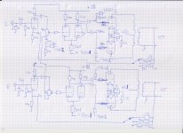
Looks like the resistor that goes from the 18K to GND is 470 Ohm in the picture of the MA-300B and it is not an original resistor in this amp, so probably 2 K is a wrong value. Gives abut -2,2 V at the 12BH7 grid. Makes more sense I think.
can send pic of resistors?In the schematic , the connection to bais 1 and 2 was not designated correctly. Bias 1 with the 1KOhm series resistor only goes to the common cathode resistors and bias 2 with the 350 Ohm series resistor goes to 300b grids and to the network connected to 12bh7 grids.
I received the bag with resistors that was supposed to be the resistor values to go into the amp, but they make no sense. All fine 1% Allan Bradly, but here stops the joy:
2x 470K
6x 100K
2x 51K
2x 47K
4x 39K
6x 1k
2x 100
2x 1M
I think the former "tech" guy , who had this amp for upgrade, is trying to prevent others from making this baby sing again!!
in this amp... ecc82 is voltage amp and has no volume control. So we have to be careful about headroom. Selection of correct resistors in ecc82 circuit can do. 10 k vs 47k in anode


This is all fine and good, but my purpose here is to RECONSTRUCT what Mactone did, not optimize or change the amp. The 10 k anode resistors is without a doubt what it is in the Mactone so I am not going to change that.
If the 12AU7 anode resistor is 10k -as in the sketch- the dissipation of this resistor is more than 2W.
Look at the pictures of the MA-300B. It is quitte clearing that the ECC 82 anode resistor is 10 K.
The rest of the amp is quite similar to the amp I have here.
3Again I want to restore the amp as it was, not discuss if the decissuons Mactone did was wiser or not.
The rest of the amp is quite similar to the amp I have here.
3Again I want to restore the amp as it was, not discuss if the decissuons Mactone did was wiser or not.
In your #61 post no 10k resistor in the list.
Try to identify which value suits to appropriate place in your assumed schematic, and it turns out what is missing.
Try to identify which value suits to appropriate place in your assumed schematic, and it turns out what is missing.
As I said in the text in post 61, those resistors are obviously not the ones that should go into this amp, but just some random values.

These -spare parts- are not AB.
Probably ISKRA (Slovenian) carbon film resistors (max. wattage is 2W).
Probably ISKRA (Slovenian) carbon film resistors (max. wattage is 2W).
Once more this proves, he did not put the correct resistors in the bag.
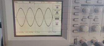
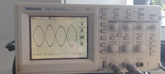
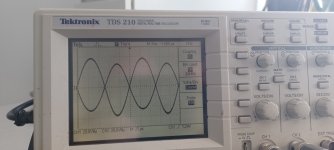
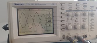
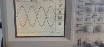
So I tested the 12BH7 circuit with different values for the resistor that determines the - Vg1 of the 12BH7 and with 10K anode resistors. I also tested it with a 33K parallel on the A1 10K resistor.
Apparently the guy who constructed this is fond of the sound of second harmonic distortion 😁
The best result , judging from the scope photos is -3,3V at G1 and 10k with 33K parallel on A1.
Attachments

w
they are not same amp.why resistors not correct?View attachment 1332121
Here are a picture of the resistors that was supposed to go inside the amp, but it is clearly not the correct values!!
The next picture shows clearly that all anode resistors should be 10K
There is no correlation between the values the types and the number of resistors. No way to put those resistors inside the amp at all.
On the other hand, the MA- 300b and MH-300B are very similar. The - Bias is the same. The feedback network the same . The power transformer the same aso, aso. Why should the anode resistors be not the same at all???
On the other hand, the MA- 300b and MH-300B are very similar. The - Bias is the same. The feedback network the same . The power transformer the same aso, aso. Why should the anode resistors be not the same at all???
I focused on the work of famous Japanese designers for years. They have a lot of courage and change.
- Home
- Amplifiers
- Tubes / Valves
- Mactone MH-300b schematic or photo